
DATA SHEET KXC-WA3-IPx-V2
Overview
Kentix IP wall readers enable contactless control of doors with a MIFARE® DESFire® RFID chip. The setup always consists of the actual wall reader and the connected Kentix AccessManager. The wall reader is connected to the AccessManager via a 4-wire connection. The AccessManager itself connects directly to a Power over Ethernet (PoE) capable network switch. To control electric strikes/motor locks, the SmartRelay offers two relay outputs and, depending on the power class of the strikes, an integrated PoE splitter with 24VDC output.
Safety instructions
No modifications of any kind may be made to Kentix GmbH products, with the exception of those described in the relevant instructions.
When installing Kentix devices, certain degrees of protection must be guaranteed.
Observe the relevant regulations for installations in the respective environment.
Only operate the products within the defined temperature range.
The instructions should be passed on to the user by the person carrying out the installation.
Kentix accepts no liability for damage to the devices or components caused by incorrect installation. Kentix accepts no liability for incorrectly programmed units.
Kentix accepts no liability for faults, material damage or other damage.
moisture, dirt and damage during transportation, storage and operation.
Only operate the products within the defined temperature range.
Installation and battery replacement may only be carried out by trained specialist personnel in accordance with the instructions.
Do not charge, short-circuit, open or heat batteries.
Observe the correct polarity when inserting the batteries.
The devices must always be operated with the batteries intended for the product.
When changing the batteries, always replace all batteries.
Dispose of old or used batteries properly.
Keep batteries out of the reach of children.
System topology
An illustration of the SmartAccess system topology can be found here.
Controls
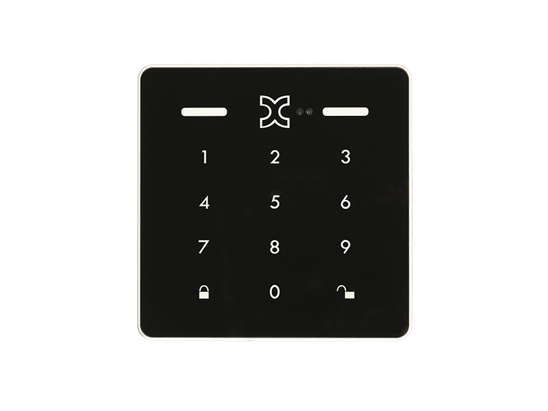
DoorLock-WA3-V2 Front view
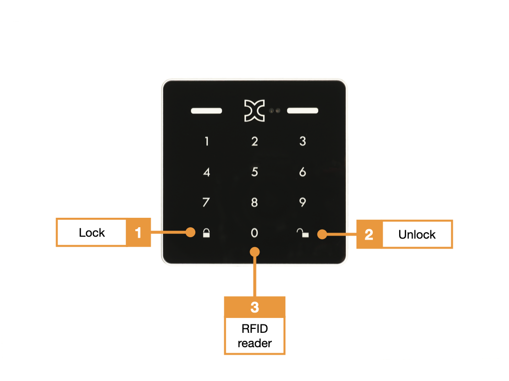
- Touch keyboard with illuminated keypad and “arm alarm” function key
- Touch keyboard with illuminated keypad and “disarm alarm” function key
- Integrated RFID reader, the entire surface serves as a reading surface.
DoorLock-WA3-V2 Rear view
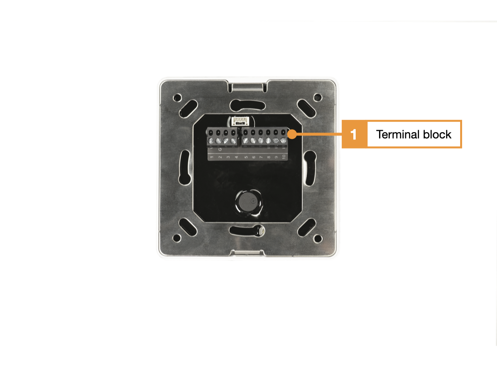
- Connection terminals, assignment see table
Terminal assignment wall reader WA3-V2
Telecommunication cable type: I-J(ST)Y 2x2x0.8mm2 is suitable for connection.
| Terminal # Reader | Function Reader | Terminal # AccessManager |
|---|---|---|
| 1 | 12-30VDC (+) | 3 (+) |
| 2 | GND (-) | 4 (-) |
| 3 | RS-485 A | 6 (BUS A) |
| 4 | RS-485 B | 5 (BUS B) |
| 5 | – | – |
| 6 | – | – |
| 7 | – | – |
| 8 | – | – |
| 9 | – | – |
| 10 | – | – |
Connection example
Two wall readers with door contacts and external door openers
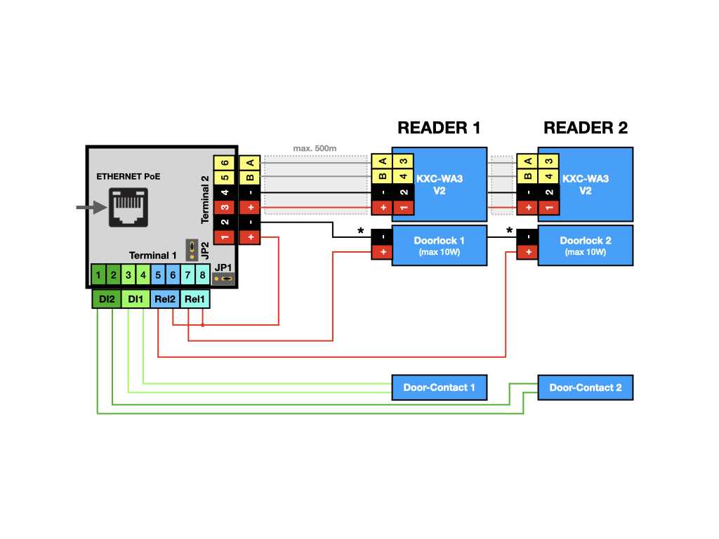
Terminal block 2 on the AccessManager (bus) is used for communication (terminals 5 and 6) and for supplying power (terminals 3 and 4) to the wall readers.
Terminal block 1 on the AccessManager (bus) contains two digital inputs (potential-free) and two relay contacts (changeover contacts). The digital inputs (terminals 1 and 2, terminals 3 and 4) are used to monitor the status of the doors (door contact). The relay contacts (terminals 5 and 6, terminals 7 and 8) can be used to control door openers. A jumper can be used to switch between normally closed and normally open contacts.
User and access management
The administration of users and access rights is done on the main device of the installation with KentixOne.
All information about the software is available in the KentixONE section.
Signaling
| Function | Signal and explanation |
| Wall reader is offline | LED flashes magenta |
| Pine input | LED flashes blue |
| Access granted | short tone, LED flashes green |
| Door is opened by time profiles | LED lights up permanently green |
| Access denied | short tone, LED flashes red |
| Zone is armed | 3 long tones, simultaneously LED flashes 3x red |
| Arming not possible | long tone, LED flashes red |
| Zone is armed | Kentix logo flashes white |