
Order-Codes:
Datasheet KXC-WA3-IPx
Overview
Kentix IP wall readers enable contactless control of doors with a MIFARE® DESFire® RFID chip. The setup always consists of the actual wall reader and the connected Kentix AccessManager. The wall reader is connected to the AccessManager via a 4-wire connection. The AccessManager itself connects directly to a Power over Ethernet (PoE) capable network switch. To control electric strikes/motor locks, the SmartRelay offers two relay outputs and, depending on the power class of the strikes, an integrated PoE splitter with 24VDC output.
Safety instructions
Installation
Installation and commissioning may only be carried out by trained specialist personnel in accordance with the instructions.
No modifications of any kind may be made to Kentix GmbH products, with the exception of those described in the relevant instructions.
When installing Kentix devices, certain degrees of protection must be guaranteed.
Observe the relevant regulations for installations in the respective environment.
Only operate the products within the defined temperature range.
The instructions should be passed on to the user by the person carrying out the installation.
Kentix accepts no liability for damage to the devices or components caused by incorrect installation. Kentix accepts no liability for incorrectly programmed units.
Kentix accepts no liability for faults, material damage or other damage.
Use of the products, transport and storage
Protect the device from
moisture, dirt and damage during transportation, storage and operation.
moisture, dirt and damage during transportation, storage and operation.
Battery powered products
Do not use the products in potentially explosive atmospheres.
Only operate the products within the defined temperature range.
Installation and battery replacement may only be carried out by trained specialist personnel in accordance with the instructions.
Do not charge, short-circuit, open or heat batteries.
Observe the correct polarity when inserting the batteries.
The devices must always be operated with the batteries intended for the product.
When changing the batteries, always replace all batteries.
Dispose of old or used batteries properly.
Keep batteries out of the reach of children.
Maintenance
Kentix devices must be checked for functionality as part of annual maintenance.
Disposal
Electrical appliances and batteries must be disposed of separately from household waste.
Controls
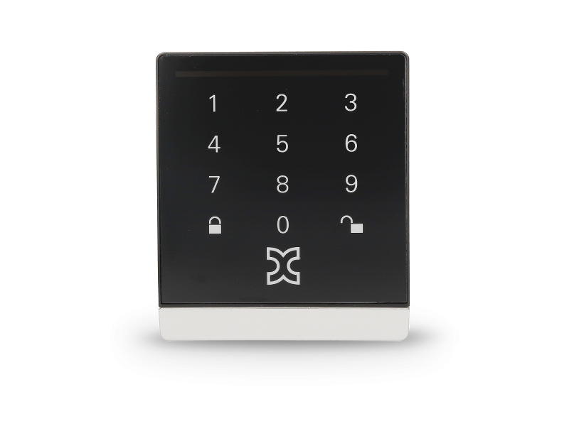
DoorLock-WA3-V1 Front view
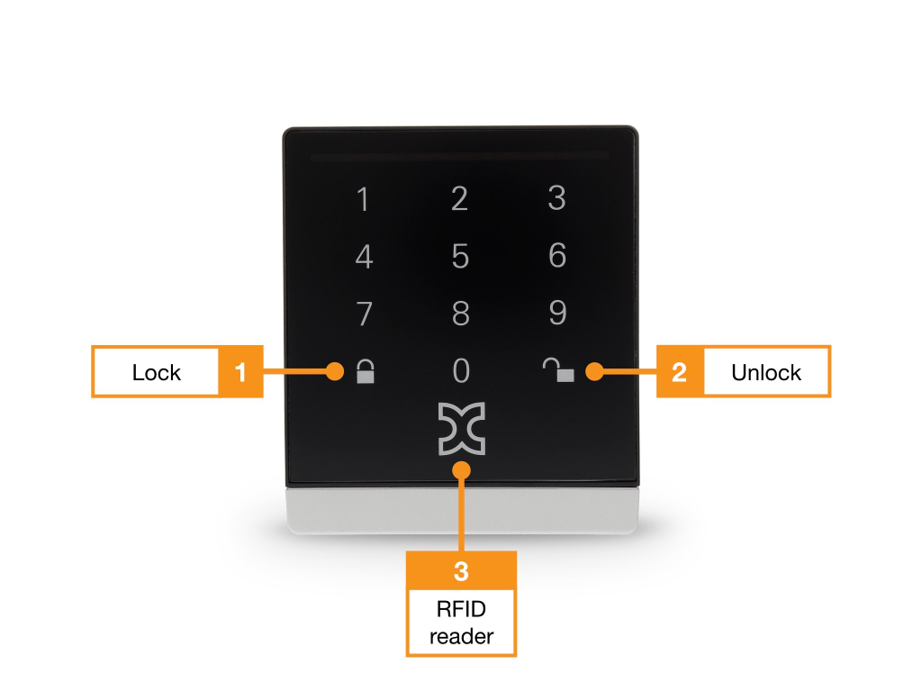
- Touch keyboard with illuminated keypad and “arm alarm” function key
- Touch keyboard with illuminated keypad and “disarm alarm” function key
- Integrated RFID reader, the entire surface serves as a reading surface.
DoorLock-WA3-V1 Rear view
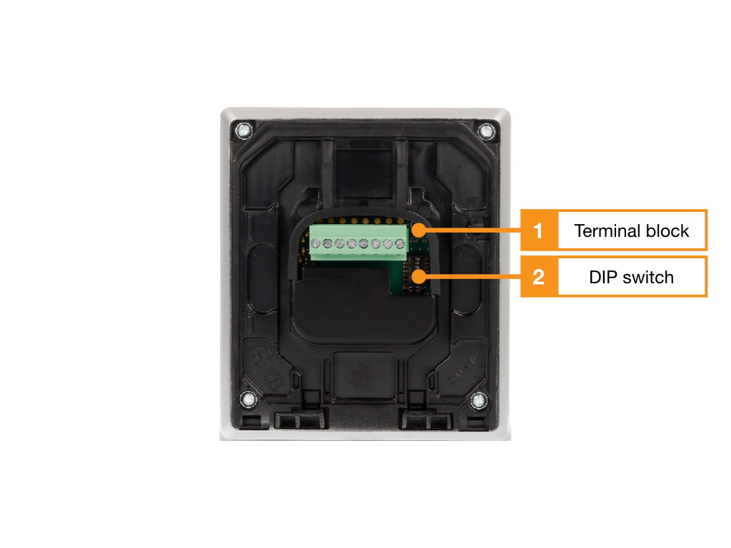
- Connection terminals, assignment see table
- DIP switch for configuring the address
Terminal assignment wall reader WA3-V1
| Clamp | Function | Connection to AccessManager (SmartRelay) |
|---|---|---|
| 1 | RS485 Data “A | Terminal Block 2, Terminal 6 (A) |
| 2 | RS485 Data “B | Terminal Block 2, Terminal 5 (B) |
| 3 | – | |
| 4 | – | |
| 5 | – | |
| 6 | – | |
| 7 | GND | Terminal Block-2, Terminal 4 ( – ) |
| 8 | 12-24V/DC | Terminal Block-2, Terminal 3 (+) |
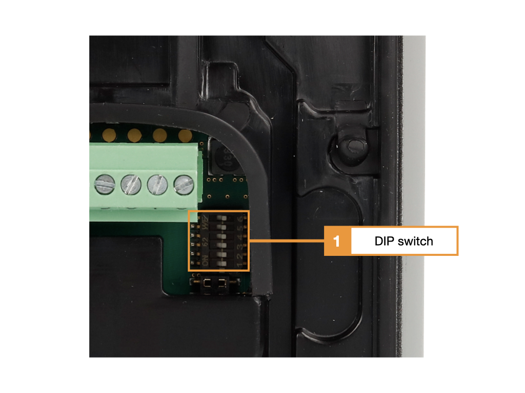
- DIP switch for configuring the address
DIP switch wall reader WA3
| DIP switch | Function |
|---|---|
| 1 | Address bit 0 (address 1: ON; address 2: OFF) |
| 2 | Address bit 1 (address 1: OFF; address 2: ON) |
| 3 | Address bit 2 (OFF) |
| 4 | Address bit 3 (OFF) |
| 5 | Baud rate (ON) |
| 6 | Terminating resistor* |
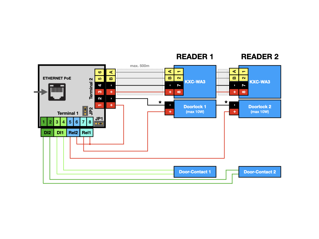
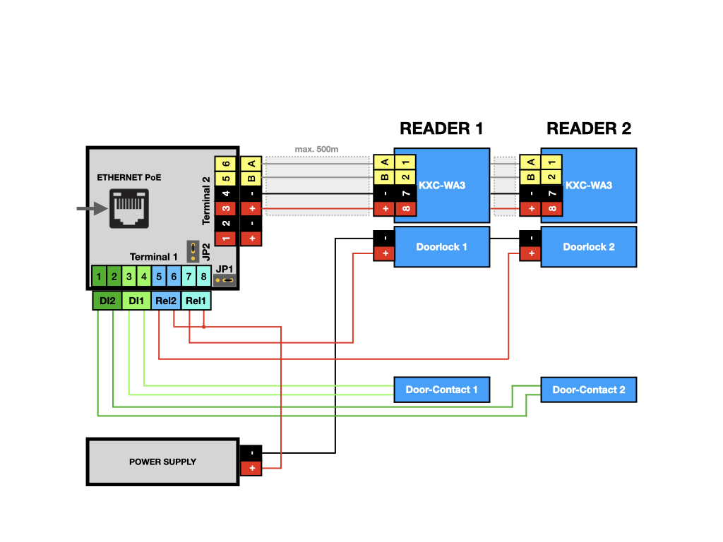
Connection examples
Two wall readers with door contacts and external door openers
Two wall readers with door contacts and external power supply for the electric strikes
User and access management
The administration of users and access rights is done on the main device of the installation with KentixOne.
All information about the software is available in the KentixONE section.
Assembly and disassembly
Flush-mounted variant
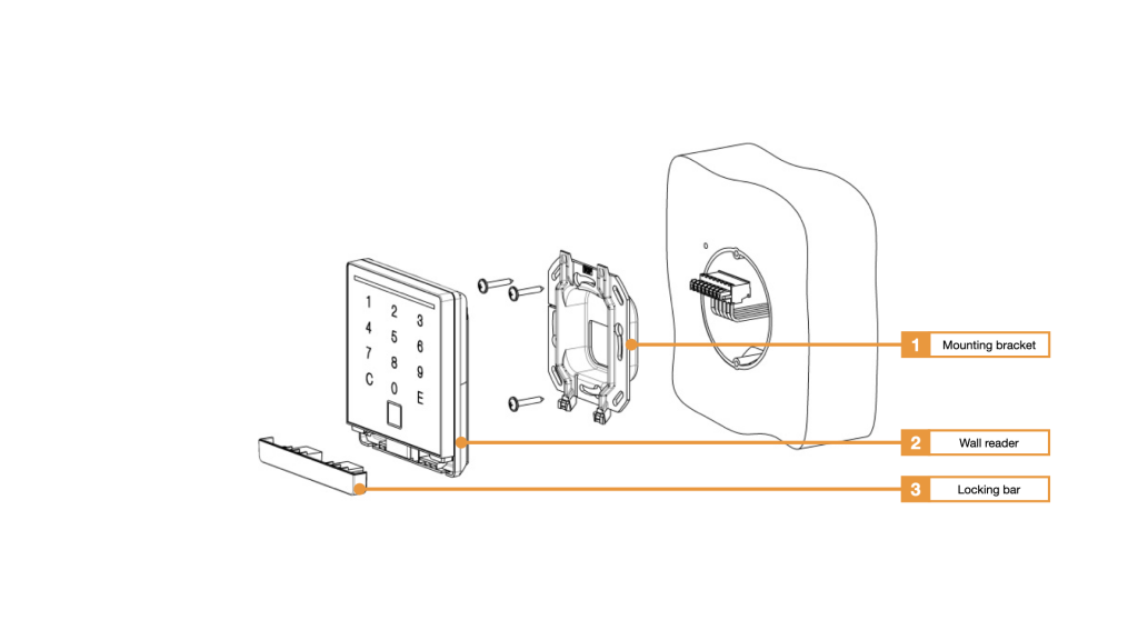
- Mounting bracket for flush-mounted application (included in scope of delivery)
- Wall reader KXC-WA3
- Locking strip
Surface-mounted version
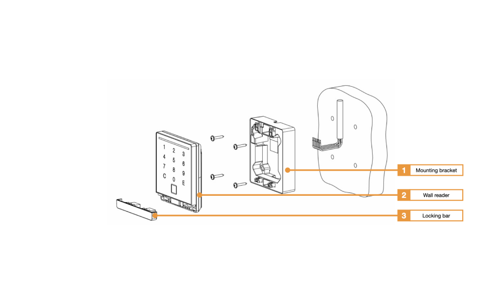
- Mounting bracket for surface-mounted applications KXC-WA3-SMC
- Wall reader KXC-WA3
- Locking strip
Dismantling
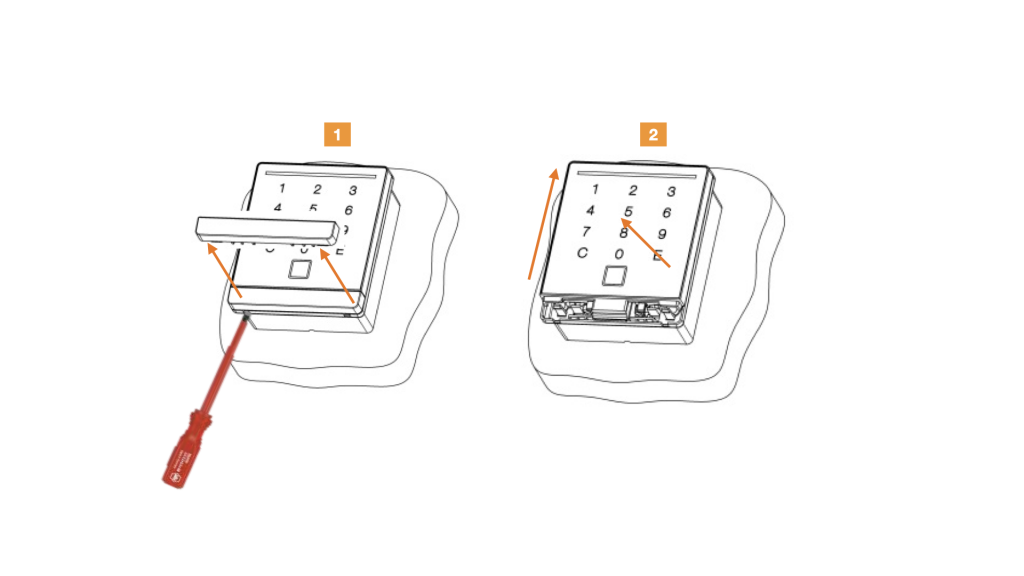
- Insert the screwdriver into the unlocking openings and unlock the lock. Pull out the locking bar.
- Push the wall reader upwards and lift it forwards.
Signaling
| Function | Signal and explanation |
|---|---|
| Wall reader is offline | LED flashes orange |
| Pine input | LED flashes blue |
| Access granted | short tone, LED flashes green |
| Door is opened by time profiles | LED lights up permanently green |
| Access denied | 3x short beep, LED flashes red |
| Zone is armed | 3 long tones, simultaneously LED flashes 3x red |
| Arming not possible | long tone, LED flashes red |
| Zone is armed | LED flashes red |