DATASHEET LEAKAGE SENSOR
Overview
The leakage sensor is used to monitor areas for leaks. A point sensor is attached to the underside of the leakage sensor for this purpose. For monitoring a larger area, the sensor can be supplied with an additional sensor cable. The sensor is connected to the SystemPort of a suitable remote station via the integrated 10-meter connection cable. All Kentix devices that are operated in one of the three operating modes Main, Sattelite or Stand-Alone Device are suitable as remote stations. Each sensor can cascade another leakage sensor so that up to 3 sensors can be connected in series. In the event of a leak, the sensor provides feedback both optically and via the digital input of the remote station.
Safety instructions
No modifications of any kind may be made to Kentix GmbH products, with the exception of those described in the relevant instructions.
When installing Kentix devices, certain degrees of protection must be guaranteed.
Observe the relevant regulations for installations in the respective environment.
Only operate the products within the defined temperature range.
The instructions should be passed on to the user by the person carrying out the installation.
Kentix accepts no liability for damage to the devices or components caused by incorrect installation. Kentix accepts no liability for incorrectly programmed units.
Kentix accepts no liability for faults, material damage or other damage.
moisture, dirt and damage during transportation, storage and operation.
Only operate the products within the defined temperature range.
Installation and battery replacement may only be carried out by trained specialist personnel in accordance with the instructions.
Do not charge, short-circuit, open or heat batteries.
Observe the correct polarity when inserting the batteries.
The devices must always be operated with the batteries intended for the product.
When changing the batteries, always replace all batteries.
Dispose of old or used batteries properly.
Keep batteries out of the reach of children.
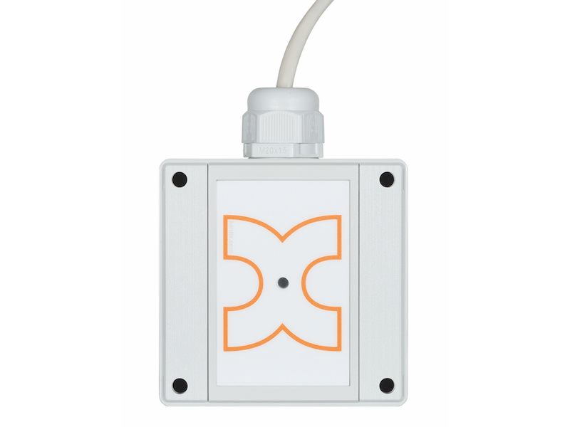
Controls
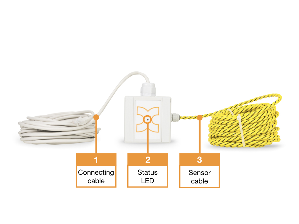
- Connection cable
- Status LED :
GREEN: POWER OK, no alarms pending
RED: Power OK, alarms pending - Sensor cable
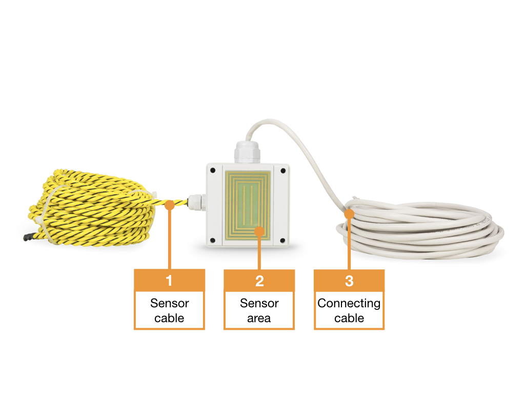
- Sensor cable
- Housing sensor
- Sensor cable
Detection and sensitivity
The housing sensor triggers an alarm even at small amounts of water of 1-2ml. The sensor cable requires approx. 10ml of water over a length of 20cm to trigger. Wetting can take place in several places, only the total wetting must be approx. 20cm.
Connection examples
Leakage sensor at SystemPort of remote terminal
Plug the connection cable of the leakage sensor into a SystemPort of the remote station. Power supply and alarming is done directly via the SystemPort.
The leakage sensor and the alarm behavior are configured via the integrated web server of the main device. Assign a suitable designation, such as “Leakage or water alarm” for the external alarm input 1 via the configuration of the remote station and set the alarm input to “Permanently active” for a permanent alarm. Additionally, change the alarm logic to “Alarmwhen open“.

Cascading of the leakage sensors
Each sensor can cascade another leakage sensor so that up to 3 sensors in total can be operated on one Kentix system port. The connection is made via a standard patch cable and can also be integrated into structured cabling.
It is important to code the sensors appropriately as middle or end devices. For this purpose, there is a microswitch in the housing with which the coding can be set accordingly.
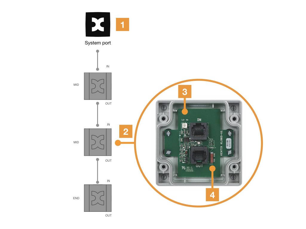
- System port of the remote terminal
- Leakage sensor
- Opened housing of the leakage sensor
- Microswitch for coding as middle or end device
Leakage sensor with sensor cable
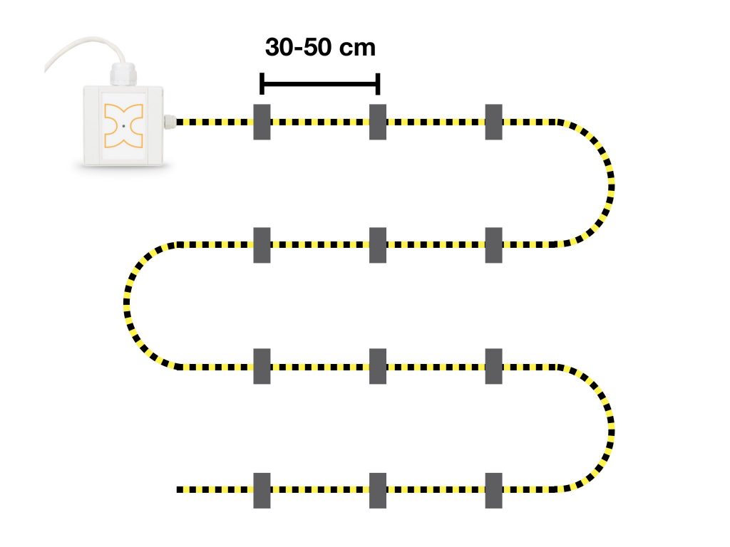
The leakage sensor with sensor cable (KLS03-ROPE10/20) is a version of the standard leakage sensor KLS03 extended by a sensor cable. This makes it possible to monitor a floor area over a wide area. With this, the entire sensor cable serves as a detector, so you can detect leaks over a length of up to 20 meters with a single sensor. The sensor cable is typically laid in a meandering pattern, in loops, across the floor. The KLS03-ROPE10/20 functions in the same way as the KLS03. On the underside of the housing there are also the sensor electrodes for point detection. It is also possible to cascade up to 3 KLS03(-ROPE) if required.
The sensor cable of the KLS03-ROPE leakage sensor must be fixed to the floor. It is recommended to use the enclosed plastic dowel clamps for a hole of 6mm. The distance between the individual clamps should be between 30cm and 50cm. If it is not possible to drill a hole for the dowel clamps, the sensor cable can also be fixed with strips of high-quality adhesive tape. At the same intervals as the dowel fastening. It is important for both types of mounting that the sensor cable rests on the ground over its entire length.