
Quick Start Manual
Overview
The extension module (system port) is used for the direct extension of Kentix devices with input/output functions, e.g. for alarm/fault messages or switching functions. The following input/output channels are available:
– Connection of up to two external messages via potential-free contacts
– Activation or switching of up to 2 external devices via relay contacts (changeover contact)
The module is connected to the Kentix system socket (RJ45) of the respective device. The extension module is supplied with power via the system socket of the remote station and does not require an external power source. The cable length between the remote station and the module should not exceed 10-20 meters. The relays are equipped with changeover contacts and can be loaded with up to 60VDC/3A, the inputs may only be connected potential-free.
Safety instructions
No modifications of any kind may be made to Kentix GmbH products, with the exception of those described in the relevant instructions.
When installing Kentix devices, certain degrees of protection must be guaranteed.
Observe the relevant regulations for installations in the respective environment.
Only operate the products within the defined temperature range.
The instructions should be passed on to the user by the person carrying out the installation.
Kentix accepts no liability for damage to the devices or components caused by incorrect installation. Kentix accepts no liability for incorrectly programmed units.
Kentix accepts no liability for faults, material damage or other damage.
moisture, dirt and damage during transportation, storage and operation.
Only operate the products within the defined temperature range.
Installation and battery replacement may only be carried out by trained specialist personnel in accordance with the instructions.
Do not charge, short-circuit, open or heat batteries.
Observe the correct polarity when inserting the batteries.
The devices must always be operated with the batteries intended for the product.
When changing the batteries, always replace all batteries.
Dispose of old or used batteries properly.
Keep batteries out of the reach of children.
Connections
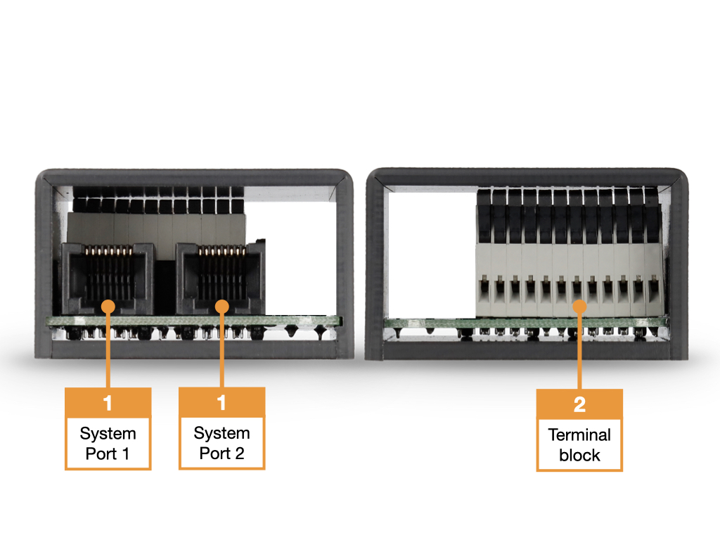
- Kentix system port (port 1, RJ45) for connection to the system port of the remote station, e.g. AlarmManager, MultiSensor (Ethernet) or AccessManager (wireless). The second socket (port 2, RJ45) serves as an output socket for forwarding the signals.
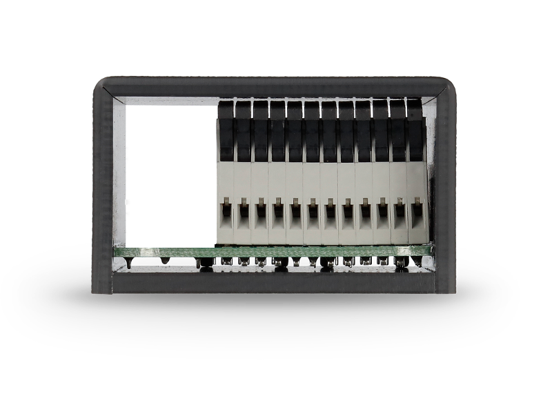
- Connection block (hinged spring terminal) for external wiring, see assignment and example wiring diagrams.
Circuit diagram with external alarms
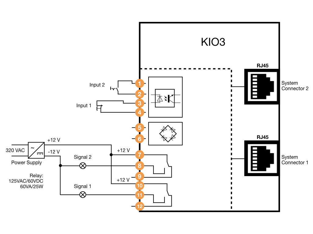
- Terminal: Digital input 2 for potential-free wiring with normally open/normally closed contact
- Terminal: Digital input 2 for potential-free wiring with normally open/normally closed contact
- Terminal: Digital input 1 for potential-free wiring with normally open/normally closed contact
- Terminal: Digital input 1 for potential-free wiring with normally open/normally closed contact
- Terminal: External power supply 24VDC or BUS (A) – Not required!
- Terminal: External power supply 24VDC or BUS (B) – Not required!
- Terminal: Relay output 2 COM (Common max 24VDC/1A), changeover contact
- Terminal: Relay output 2 NC (Normally Closed)
- Terminal: Relay output 2 NO (Normally Open)
- Terminal: Relay output 1 COM (Common max 24VDC/1A), changeover contact
- Terminal: Relay output 1 NC (Normally Closed)
- Terminal: Relay output 1 NO (Normally Open)