
DATASHEET KXC-KN1, KXC-KN2
Overview
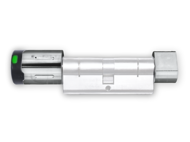
The Kentix DoorLock-DC Basic is a battery-operated electronic knob cylinder with radio control. The knob cylinder is designed for locking and unlocking locks in building doors. Depending on the product variant, the knob cylinder can be used indoors and outdoors. RFID transponder carriers with MIFARE®DESFire® can be used as keys.
The electronic knob cylinder is networked by radio with an AccessManager radio. Up to 16 DoorLock radio components can be programmed into one AccessManager radio. The configuration is done via the integrated web server of the main device (operating mode: Main-Device).
Safety instructions
No modifications of any kind may be made to Kentix GmbH products, with the exception of those described in the relevant instructions.
When installing Kentix devices, certain degrees of protection must be guaranteed.
Observe the relevant regulations for installations in the respective environment.
Only operate the products within the defined temperature range.
The instructions should be passed on to the user by the person carrying out the installation.
Kentix accepts no liability for damage to the devices or components caused by incorrect installation. Kentix accepts no liability for incorrectly programmed units.
Kentix accepts no liability for faults, material damage or other damage.
moisture, dirt and damage during transportation, storage and operation.
Only operate the products within the defined temperature range.
Installation and battery replacement may only be carried out by trained specialist personnel in accordance with the instructions.
Do not charge, short-circuit, open or heat batteries.
Observe the correct polarity when inserting the batteries.
The devices must always be operated with the batteries intended for the product.
When changing the batteries, always replace all batteries.
Dispose of old or used batteries properly.
Keep batteries out of the reach of children.
System topology
An illustration of the SmartAccess system topology can be found here.
Mastercard set

The master card set is used to prepare the DoorLock devices with radio for operation. All IP wall readers that are connected via the SmartRelay are excluded. With the service key card, the radio components such as knobs, door handles or wall readers are integrated into the radio network and the communication is encrypted. Only one master card set is required per system or installation. We recommend using an extra set of master cards for each project.
Resetting the components with the service key
When resetting wireless locking components, the programmed service key is retained. All additional cards such as battery replacement and removal cards for BASIC models and stored authorizations for emergency access are deleted. This step is used for troubleshooting and diagnostics on site.
Our support team will ask for the number of the corresponding system card for any tests/repairs at the factory.
- The Servicekey card (YELLOW) in front of the reader unit of the device and hold it there until programming mode is automatically terminated. Then briefly (approx. 2 seconds) remove the card.
- Hold the service key in front of the reader again and leave it there. The DoorLock device signals the deletion process with short tones. Leave the service key card in front of the reader until the signaling stops.
- The device or card set has been reset and can be taught in again.
Commissioning
Prepare device
- Pull off knob cover (See battery change)
- Pull out the lock from the battery compartment
Set up programming card set
- Hold the service key (yellow) in front of the knob for approx. 1 second to activate.
- Hold the service key again briefly in front of the knob. The service key is now programmed.
- Hold the service key briefly in front of the knob again to start the programming mode.
- Hold the battery replacement card(green) in front of the knob until a signal tone sounds.
- Hold the disassembly card(blue) in front of the knob until a signal tone sounds.
- Hold the service key in front of the knob to complete the process.
User and access management
The administration of users and access rights is done on the main device of the installation with KentixOne.
All information about the software is available in the KentixONE section.
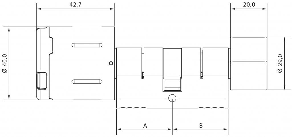
Dimensions DoorLock KXC-KN1
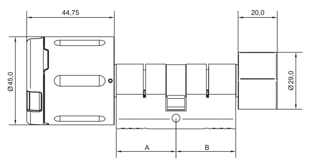
Dimensions DoorLock KXC-KN2
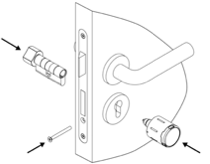
Mounting
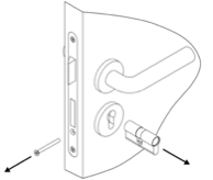
Only a few steps are required for the installation. Please proceed as follows:
| Step | Note |
|---|---|
| Remove the faceplate screw and pull the existing cylinder out of the door. | Each Kentix profile cylinder comes with a new forend screw. |
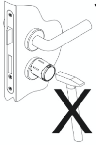
| Insert the Kentix profile cylinder into the door. Then insert the face plate screw and tighten it hand-tight, do not use a cordless screwdriver with a high torque. | The mechanical knob is already attached to the profile cylinder. Therefore, insert the profile cylinder into the guide from the inside of the door. |
| Insert the RFID radio knob into the cylinder until it clicks into place. | |
| The installation is completed. If not already done, the knob can now be programmed with the card set. | Programming of the master card set in the knob should already be done before installation on the door. |
Operation
Battery warning
When the power of the batteries decreases, audible and visual warnings are generated by the device. This happens with decreasing battery power in 3 phases, during which, in addition to the warnings, the function of the device is limited. This is done in order to conserve the batteries as much as possible in the final stages and to allow them to be changed.
| Phase | Signaling | Function | Urgency |
| Phase 1 | 5 short tones, simultaneously LEDs flash 5x red | Full function | A battery change will be necessary soon. |
| Phase 2 | 5 short tones, simultaneously LEDs flash 5x red | 5 seconds delay of engagement, at the same time LEDs flash green | A battery change must be performed immediately. |
| Complete emptying | No signaling | No function | A battery change must be performed immediately. |
Battery change
Hold the battery replacement card in front of the knob module – the knob module moves to the battery replacement position. It may be necessary to wake up the knob module by turning it on before this step.
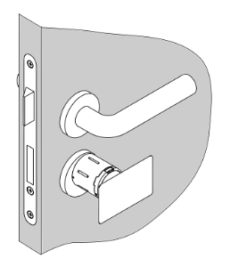
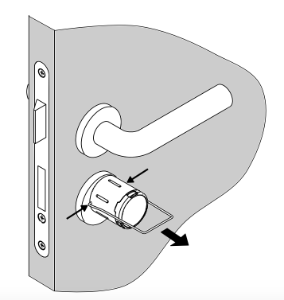
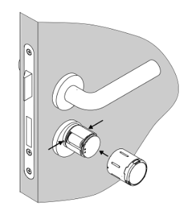
Simultaneously press in the now unlocked case locking pins of the knob module with the battery replacement tool and pull off the case.
Remove used batteries and insert new batteries, paying attention to polarity.
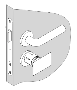
Press in the locking pins and push the knob module sleeve back on. Make sure that the locking pins are properly engaged in the sleeve.
After the battery change, the knob module is still in the battery change position. By presenting the battery replacement card or an authorized key again, the knob module moves back to the home position.
Battery change with low power adapter
If the battery of the DoorLock-DC Basic is completely discharged, the knob no longer shows any reactions (LEDs and signal tones). In the last phase of the drained battery condition, the knob always moves to the position where the pins can be pushed in to change the battery. If this is not the case, the low-power adapter (ORDER-CODE:KXC-BAT2) is required.
Application of the low power adapter
- Remove the plastic cover with the suction cup
- Hold the low-power adapter to the contacts of the knob and remain in this position
- Hold battery replacement card between knob and low-power adapter
- Remove the low-power adapter and press in the two opposite pins with battery change pliers
- By pulling, the cover of the knob can be removed and the battery can be taken out
- Insert new battery and bring the knob shell into the correct position
- Fix pins with battery change card
- Fasten plastic cover with logo
The following video shows the procedure for changing the battery with low-power adapter. You can find more information about the low-power adapter here: Low Power Adapter.
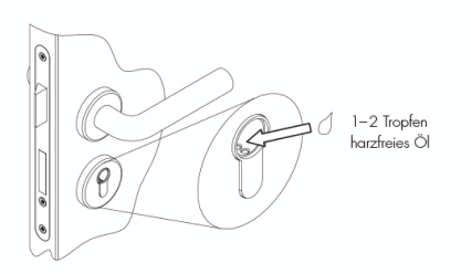
Maintenance
Maintenance and care of the cylinders or the entire lock should be performed at least once a year (more often in case of heavy use). Care must be taken to ensure that all door components move smoothly.
Battery Maintenance Software
The DoorLock’s battery maintenance feature must be enabled in the KentixONE configuration interface, version 8.6.0 or later. After the initial setup of the DoorLock and after every battery replacement, this feature must be activated to ensure trouble-free operation. Afterward, at least one successful transaction must be completed to finalize the activation.
Signaling
| Function | Signal (acoustic and visual) and explanations |
|---|---|
| First booking after commissioning | long tone and orange LED |
| Programming mode start | Long tone followed by a short tone |
| Programming mode | LEDs flash green |
| Programming mode end | short tone followed by a long tone |
| Key taught | 2 short tones, LEDs light up green |
| Key authorized | LEDs light green |
| Key not authorized | long low tone, LEDs light up red |
| Emergency access | no sounds, only the green LED flashes |
| Battery warning phase 1 | 5 short tones, simultaneously LEDs flash 5x red |
| Battery warning phase 2 | 5 short tones, at the same time LEDs flash 5x red, then 5s delay of engagement, at the same time LEDs flash green |
| Battery warning phase 3 | 5 short beeps, simultaneously LEDs flash 5x red, no engagement, but battery change position |
| Coupling error | 5 long tones, 2 short tones. Contact support at support@kentix.com |