
DATASHEET ACCESSMANAGER BUS
KentixONE Operating mode
| SiteManager Operation | Stand-Alone Operation |
|---|---|
Overview
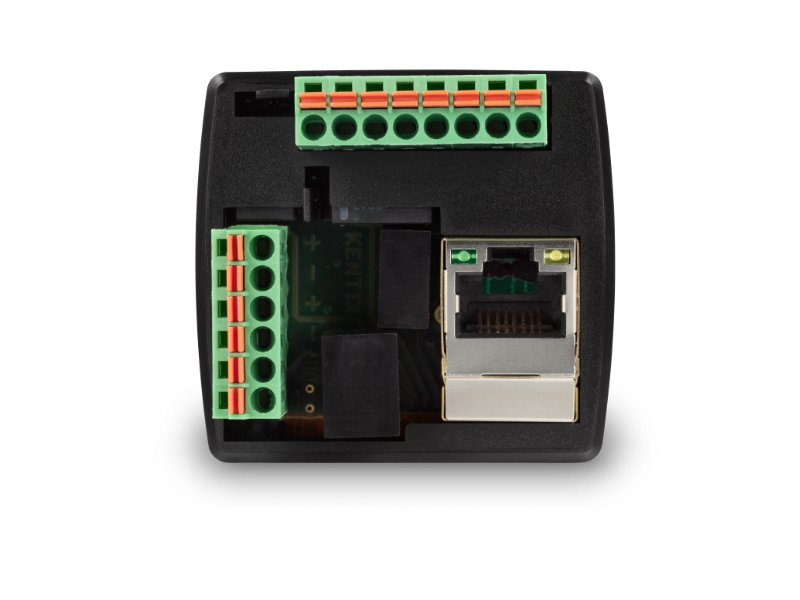
The Kentix AccessManager (Bus) is the management unit for wired Kentix DoorLock components such as wall readers (DoorLock-WA) or rack locks (DoorLock-RA4). The AccessManager is network-compatible and is supplied with power via Power over Ethernet (PoE). The AccessManager has an integrated 24VDC PoE splitter to supply the connected readers and locks with power.
The AccessManager can be operated as a main device (operating mode: Main Device) or as part of a network (operating mode: Satellite Device) with other AccessManagers. The KentixONE software is already integrated via the integrated web server (HTTPS). Configuration is performed via web browser and, depending on the operating mode, locally on the AccessManager itself or on a central instance such as the SiteManager or AlarmManager.
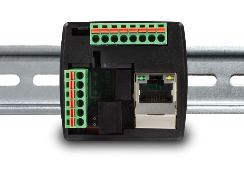
The AccessManager can be mounted on a standard DIN rail or alternatively in a 60mm switch box.
Safety instructions
No modifications of any kind may be made to Kentix GmbH products, with the exception of those described in the relevant instructions.
When installing Kentix devices, certain degrees of protection must be guaranteed.
Observe the relevant regulations for installations in the respective environment.
Only operate the products within the defined temperature range.
The instructions should be passed on to the user by the person carrying out the installation.
Kentix accepts no liability for damage to the devices or components caused by incorrect installation. Kentix accepts no liability for incorrectly programmed units.
Kentix accepts no liability for faults, material damage or other damage.
moisture, dirt and damage during transportation, storage and operation.
Only operate the products within the defined temperature range.
Installation and battery replacement may only be carried out by trained specialist personnel in accordance with the instructions.
Do not charge, short-circuit, open or heat batteries.
Observe the correct polarity when inserting the batteries.
The devices must always be operated with the batteries intended for the product.
When changing the batteries, always replace all batteries.
Dispose of old or used batteries properly.
Keep batteries out of the reach of children.
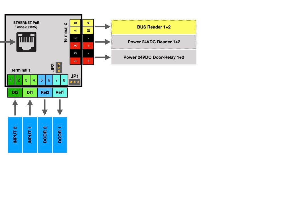
Connection and operating elements
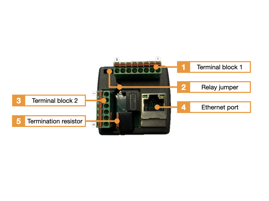
- Terminal block 1 (terminal 1-8, IO terminal with relay 1+2, digital input 1+2)
- Jumper for switching the logic for relay output 1+2 (NC, NO)
- Terminal block 2 (terminal 1-6, BUS for RFID reader, PoE splitter 24VDC)
- Ethernet port with PoE power supply, Class 3 (12.95W)
- The terminating resistor (final resistor) is switched on or off as required.
| Terminal block 1 | Function connection |
|---|---|
| 1 | Digital input DI 2 (for potential-free wiring, e.g. door contact) |
| 2 | Digital input DI 2 (For potential-free wiring) |
| 3 | Digital input DI 1 (For potential-free wiring) |
| 4 | Digital input DI 1 (For potential-free wiring) |
| 5 | Relay 2 NO/NC (Default=NO) |
| 6 | Relay 2 COM (relay power max. 60VDC/1A) |
| 7 | Relay 1 NO/NC (Default=NO) |
| 8 | Relay 1 COM (relay power max. 60VDC/1A) |
| Terminal block 2 | Function connection |
|---|---|
| 1 | (+) 24VDC (power supply door opener, max. 0.5A) |
| 2 | (-) GND (power supply door opener, max. 0.5A) |
| 3 | (+) 24VDC (power supply RFID reader) |
| 4 | (-) GND (power supply RFID reader) |
| 5 | BUS-B (communication line to RFID reader) |
| 6 | BUS-A (communication line to RFID reader) |
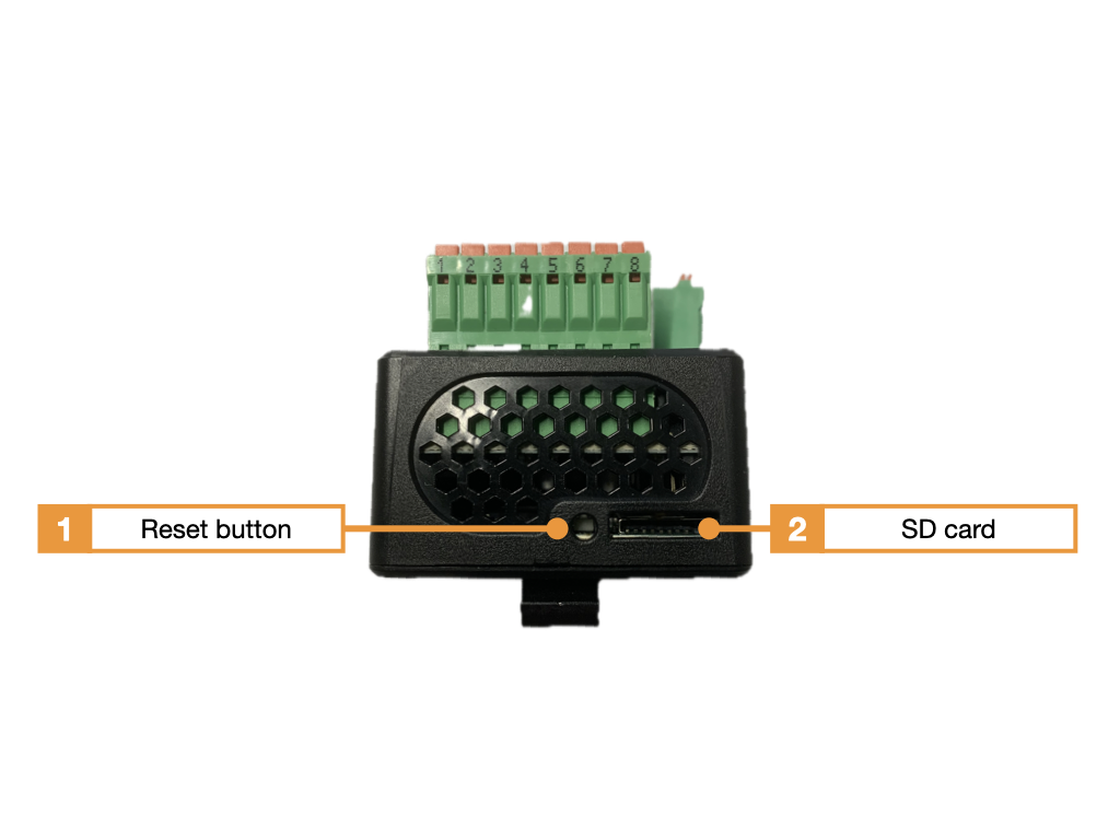
- Reset button
- MicroSD card slot
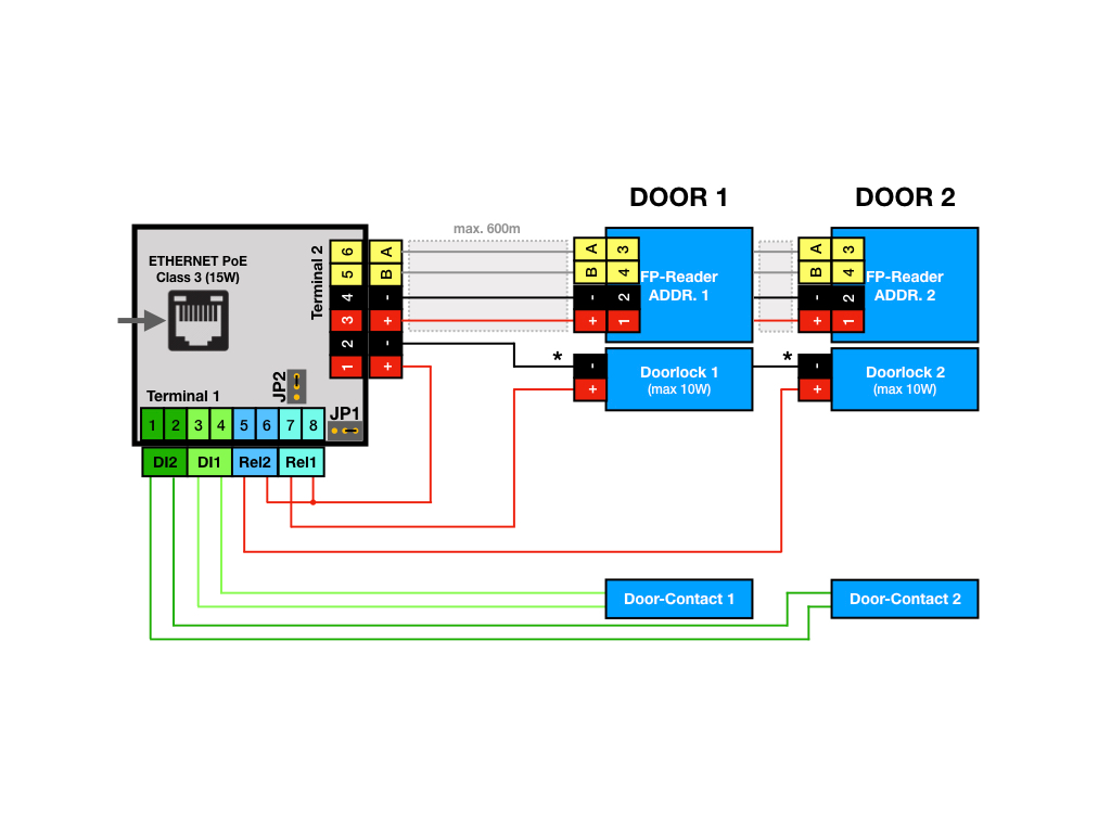
Wiring diagram SmartRelay with RFID wall reader
Wiring example and terminal diagram for two doors with PoE power supply for the electric strikes
The following wiring diagram shows the basic wiring of the AccessManager with two wall readers and two door contacts for monitoring the door status. The readers are connected via a BUS (RS485) with a total cable length of up to approx. 500m. We recommend J-Y(ST)Y-2x2x0.8mm2 as the connecting cable between the AccessManager and the wall reader. The AccessManager is supplied with power via Ethernet PoE, whereby the module provides two 24VDC voltage outputs via the integrated PoE splitter to supply the readers and the locking control unit. When supplying power to the locks (door opener, motorized lock, magnetic holder), please note that the splitter can supply a maximum of 10W power. If more power is required for control, the locks must be supplied with power via an external power supply unit. The advantage of using the splitter and PoE is the simultaneous emergency power supply for the door control unit when using a UPS on the PoE-supplying switch.
See also the Kentix video tutorial“KentixONE First Steps Part 7: Adding RackLock RA4 and Wall Reader IP“.
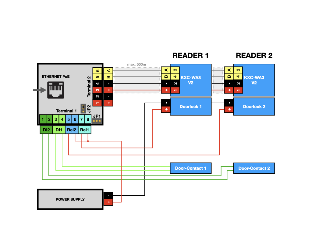
Wiring example and terminal diagram for two doors with external power supply to the electric strikes
As soon as the electric strikes have a total current consumption of more than 0.5 A (at 24 V DC), they must be supplied by an additional voltage source. The voltage source must supply the voltage and power required for the electric strike. The positive voltage path leads from the voltage source via the relays to the electric strikes. The relay logic can be set via jumpers.
Wiring example and terminal diagram for controlling external intruder alarm systems (alarm systems)
A corresponding software configuration in KentixOne makes it possible to control external intruder alarm systems with forced operation. In this context, inevitability means that the alarm system or an alarm zone can only be armed if, for example, all windows/doors are closed and the alarm system gives the AccessManager permission to do so. The wiring is always the same in principle, depending on the software setting, the evaluation can be carried out with or without a query of the setting. The inputs must always be wired potential-free, the logic levels for the transfer are always continuous levels, not pulses. One alarm zone can be controlled per AccessManager; several doors in one zone require a corresponding number of AccessManagers.
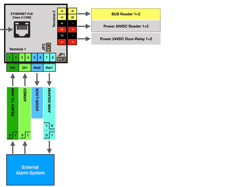
The digital inputs of the AccessManager can be used to signal the arming of an external alarm system. Digital input 2 is used for the arming signal (forced operation) and digital input 1 for zone arming. The relays are used to arm (disarm) the alarm system (relay 1) and to control the door opener (relay 2). All levels are continuous levels (no pulses) and remain permanently switched on according to the switching time. The relay logic can be changed via jumpers.
Use of version 2 wall readers
The AccessManager uses different communication protocols to communicate with the wall readers, depending on the type/version. The appropriate communication protocol must be selected for BUS communication between the AccessManager and the version 2 wall reader. This can be changed in the web interface of the AccessManager (ART: KXP-2-RS) under the menu item “SMARTACCESS -> General settings -> Wall reader”. Version 2 wall readers can be clearly identified by the sticker on the wall reader. Wall readers of both versions cannot be operated simultaneously on one AccessManager.
Factory settings
For initial configuration, use the IP address printed on the device or the address assigned via DHCP in a web browser (HTTPS). Please note the network settings of your connected PC.
The factory IP addresses at a glance:
| SiteManager and AlarmManager | 192.168.100.222 |
| MultiSensor | 192.168.100.223 |
| AccessManager | 192.168.100.224 |
| PowerManager | 192.168.100.225 |
| SmartPDU | 192.168.100.226 |
| Leakage sensor | 192.168.100.227 |
Reset to factory settings
- Restart the device (disconnect and reconnect the power supply).
- The status LED lights up briefly and then goes out.
- As soon as the status LED lights up green continuously, press and hold the reset button for 15 seconds until the device emits an acoustic feedback.
- The device loads the factory settings and performs a restart.
- After approx. 2 minutes, the device can be reached with the factory settings.
Configuration with KentixONE
The device is configured via the web browser in KentixONE. The device must be accessible to the central KentixONE instance on the network side. Depending on the device type, a communication key and the IP address or DHCP name of the central KentixONE instance must also be set on the device (MultiSensors, AccessManager, SmartPDU). IP cameras or IO modules, on the other hand, can be integrated directly into KentixONE.
All information about the software can be found in the KentixONE section and the associated documentation.