Replaced by: KXC-WA3-V2-OUTDOOR-IP1, KXC-WA3-V2-OUTDOOR-IP
DATASHEET KXC-WA3-OUTDOOR-IP1, KXC-WA3-OUTDOOR-IP
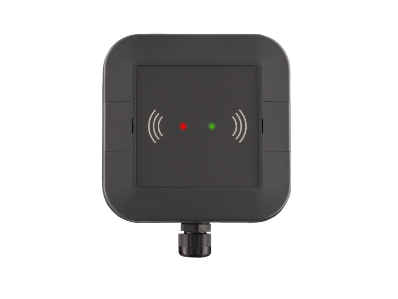
The IP wall readers enable contactless unlocking of doors with an RFID chip and/or PIN code as two-factor authentication for models with an integrated keypad. The IP wall readers always consist of the actual wall reader and the Kentix SmartRelay. The wall readers are connected using a SmartRelay and can then be connected to an AccessManager (KXP-2-RS) via the Manager/Satellite mode. The wall reader is available in various designs for indoor/outdoor, surface-mounted/flush-mounted or for installation in intercom systems.
Controls
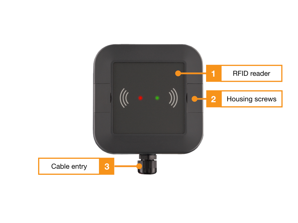
WA3 Outdoor View Front

- Integrated RFID reader, the entire surface serves as a reading surface
- Housing screws, behind the black covers on both sides
- Cable input, the cables are fed into the device here
Functional elements front
- Integrated RFID reader, the entire surface serves as a reading surface
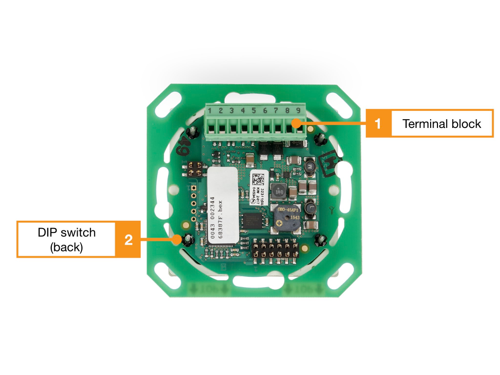
WA3 interior view

- Terminal block 1, see wiring diagram
- DIP switch for configuring the address
Terminal assignment WA3 Outdoor
| Clamp | Function |
|---|---|
| 1 | – |
| 2 | – |
| 3 | – |
| 4 | – |
| 5 | – |
| 6 | RS485 Data “A” |
| 7 | RS485 Data “B” |
| 8 | 8-30 V/DC |
| 9 | GND |
DIP switch WA3 Outdoor and WA2
| DIP switch | Function |
|---|---|
| 1 | Address 1 (1=ON, 2=OFF) |
| 2 | Address 2 (1=OFF, 2=ON) |
| 3 | – |
| 4 | – |
| 5 | Baud rate (5=ON) |
| 6 | – |
| 7 | – |
| 8 | Terminating resistor* |
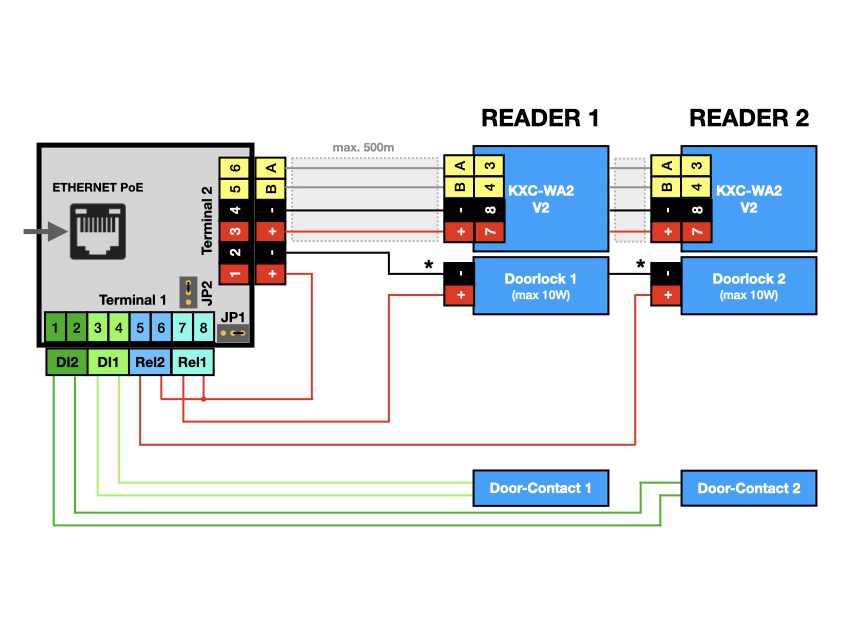
Connection example
One or two wall readers with door contacts and external door openers
Terminal 2 on the AccessManager provides communication via the data bus and the supply of operating voltage for the wall readers. (terminals 3-6). Terminal 2 serves as a common potential for the power supply of door openers with the PoE supply voltage of the AccessManager.
Terminal 1 is used for connection of potential-free contacts (“door contacts”, terminals 1-4) and switching of door openers by relay 2 (5-6) and relay 1 (7-8). Relay 1 and 2 switch terminal 1 to terminal 2 to common potential (terminal2, terminal 2).

User and access management
The administration of users and access rights is done on the main device of the installation with KentixOne.
All information about the software is available in the KentixONE section.