
DATASHEET KXC-WA5-IP2
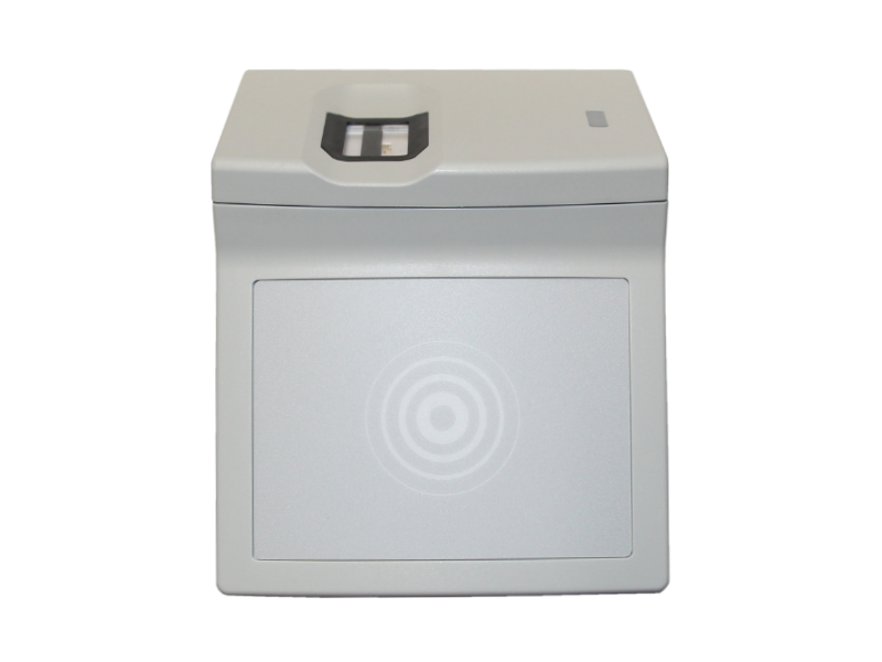
The fingerprint reader enables unlocking doors using a fingerprint and RFID card/token. This is a two-factor authentication (2FA), where both components are always required to open a door. Not only one finger or only the RFID card can be used. It is connected using a SmartRelay and can then be connected to an AccessManager (KXP16) using Manager/Satellite mode. The wall reader is surface mounted.
Safety instructions
No modifications of any kind may be made to Kentix GmbH products, with the exception of those described in the relevant instructions.
When installing Kentix devices, certain degrees of protection must be guaranteed.
Observe the relevant regulations for installations in the respective environment.
Only operate the products within the defined temperature range.
The instructions should be passed on to the user by the person carrying out the installation.
Kentix accepts no liability for damage to the devices or components caused by incorrect installation. Kentix accepts no liability for incorrectly programmed units.
Kentix accepts no liability for faults, material damage or other damage.
moisture, dirt and damage during transportation, storage and operation.
Only operate the products within the defined temperature range.
Installation and battery replacement may only be carried out by trained specialist personnel in accordance with the instructions.
Do not charge, short-circuit, open or heat batteries.
Observe the correct polarity when inserting the batteries.
The devices must always be operated with the batteries intended for the product.
When changing the batteries, always replace all batteries.
Dispose of old or used batteries properly.
Keep batteries out of the reach of children.
Controls
DoorLock-WA5-IP front side
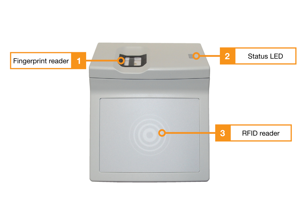
- Fingerprint sensor for creating the templates in the learning process and opening the door using the RFID card and fingerprint
- Status LED for signaling the various modes and states of the reader
- Integrated RFID reader, the entire surface serves as a reading surface
DoorLock-WA5-IP Backside
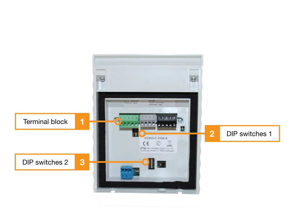
- Connection terminals, for assignment see table
- DIP switch 1, for configuration see table
- DIP switch 2, for configuration see table
Terminal assignment
| Clamp | Function |
|---|---|
| 1 | 10-30V/DC, max. 3,5VA |
| 2 | GND |
| 3 | RS485 Data “A |
| 4 | RS485 Data “B |
| 5 | Reference potential |
DIP switch 1
| DIP switch 1 | Function |
|---|---|
| 1 | Terminating resistor* (120 Ohm) |
| 2 | – |
DIP switch 2
| DIP switch 2 | Function |
|---|---|
| 1 | Address 1 (1=ON, 2=OFF) |
| 2 | Address 2 (1=OFF, 2=ON) |
| 3 | – |
| 4 | – |
| 5 | – |
| 6 | 6=ON (for baud rate 19200) |
| 7 | 7=OFF (for baud rate 19200) |
| 8 | – |
Teach-in process (Enrolment)
Starting the enrolment process
- You start the enrolment process directly in the user’s settings in KentixOne
- To do this, press the + symbol next to the RFID field and then select the fingerprint reader on which the enrolment process is performed
- The fingerprint reading surface signals the start of the enrolment process by glowing red
Teach-in of the fingers (enrolment process)
- Place the desired finger on the fingerprint reading surface. The successful reading process is confirmed with a signal tone
- Place your finger on the fingerprint reading surface again until you hear the beep.
- Place your finger on the fingerprint reading surface a third time until you hear the beep.
- Repeat this process (1-3) with a second finger
- After the third reading process of the second finger, the RFID card must be held in front of the RFID reading surface.
Storage process on RFID card and completion of the enrolment process
- Hold the RFID card in front of the RFID reader again.
- Now place your finger on the reading area once again in conclusion
- The successful write process is confirmed by a green status LED and a beep.
Opening procedure
- Hold the RFID card in front of the RFID reading surface
- The fingerprint reader is activated and the reading area lights up
- Place the taught finger on the reader. The successful operation is confirmed by a green glow of the status LED and a beep.
Detailed wiring and terminal diagram for two doors with two fingerprint readers
The following connection diagram shows the general wiring of the SmartRelay module with two wall readers and two door contacts for monitoring the door status. The readers are connected via a BUS (RS485) with a total cable length of up to approx. 600m. We recommend I(ST)Y-2x2x0.8 as the connection cable between SmartRelay and reader. The SmartRelay module is powered via Ethernet PoE. As a PoE splitter, the module provides two 24VDC voltage outputs to supply the readers and the lock control. When powering the locks (door opener, motor lock, magnetic holder), note that the splitter can supply a maximum of 10W of power. If more power is required for control, the locks must be supplied with power via an external power supply unit. The advantage of using the splitter and PoE is the simultaneous emergency power supply of the door control when using a UPS at the PoE supplying switch.
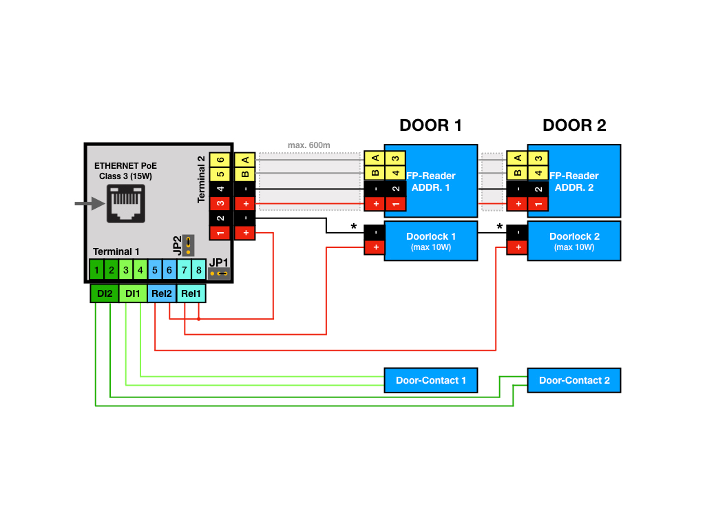
- The two readers are always supplied with voltage from the SmartRelay module. Power supply and communication bus (A+B) are routed in one line.
- The two relays (Rel1+2) can be set to the required logic NC/NO (Normally Closed/Normally Opened) via jumpers.
- The two door contacts at input 1+2 (DI1+2) require a potential-free contact (e.g. reed contact) for connection to DI1+2.
- *The power supply by the PoE Splitter can be replaced by an external power supply. This is necessary if the splitter does not supply the appropriate voltage (24VDC) or the required power (>10W).