
Replaced by: KXC-WA2-V2-IP1, KXC-WA2-V2-IP2
DATASHEET KXC-WA2-IP1, KXC-WA2-IP2
The IP wall readers enable contactless unlocking of doors with an RFID chip and/or PIN code as two-factor authentication. The IP wall readers always consist of the actual wall reader and the Kentix SmartRelay. The wall readers are connected using a SmartRelay and can then be connected to an AccessManager (KXP16) via Manager/Satellite mode. The wall reader is available in various designs for indoor/outdoor, surface-mounted/flush-mounted or for installation in intercom systems.
A Kentix AccessManager for cable readers (KXP-2-RS) is required to operate wall readers. Information about the relay and circuit diagrams including examples can be found here: Kentix SmartRelay (KXP-2-RS)
To be able to switch alarm zones on a wall reader, the following requirements must be met:
- An AlarmManager must be connected in the AccessManager configuration.
- The authorization to switch alarm zones must be activated in the user settings of the user.
- The user must be assigned a PIN and/or RFID token. The alarm zone concerned must be selected in the configuration of the wall reader.
If the prerequisites are fulfilled, the key for arming or disarming can be pressed and then the PIN can be entered or the booking can be carried out with the token. If the action is successful, the LED lights up green and the zone is switched.
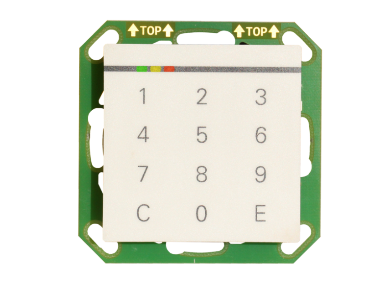
Controls
WA2 Front view
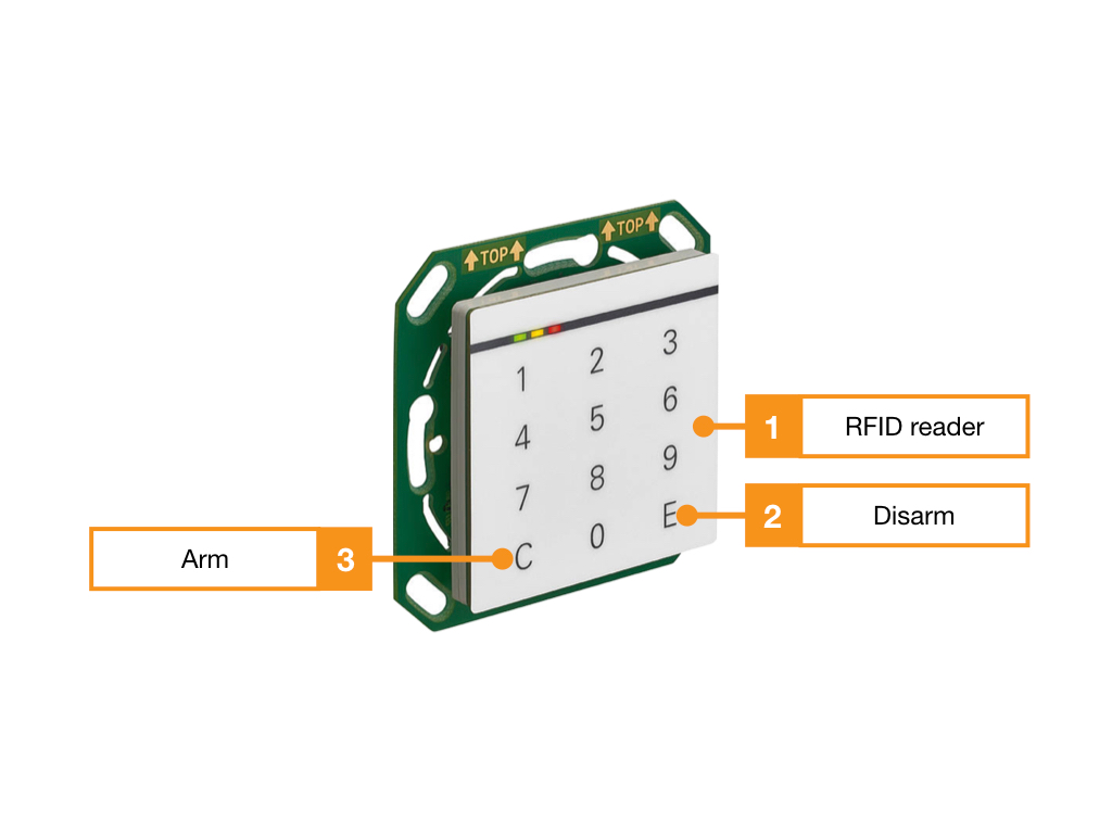
- Integrated RFID reader, the entire surface serves as a reading surface
- Button for disarming alarm zones (only in connection with Kentix AlarmManager)
- Button for arming alarm zones (only in connection with Kentix AlarmManager)
WA2 Internal elements
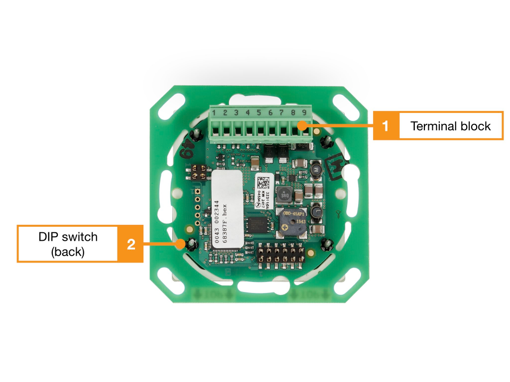
- Terminal block 1, see wiring diagram
- DIP switch for configuring the address
Terminal assignment WA2
| Clamp | Function |
|---|---|
| 1 | – |
| 2 | – |
| 3 | – |
| 4 | – |
| 5 | – |
| 6 | RS485 Data “A |
| 7 | RS485 Data “B |
| 8 | 8-30 V/DC |
| 9 | GND |
DIP switch WA2
| DIP switch | Function |
|---|---|
| 1 | Address 1 (1=ON, 2=OFF) |
| 2 | Address 2 (1=OFF, 2=ON) |
| 3 | – |
| 4 | – |
| 5 | Baud rate (5=ON) |
| 6 | – |
| 7 | – |
| 8 | Terminating resistor* |
User and access management
The administration of users and access rights is done on the main device of the installation with KentixOne.
All information about the software is available in the KentixONE section.