

DATA SHEET SmartPDU-40U
KentixONE Operating mode
| SiteManager Operation | Stand-Alone Operation |
|---|---|
Overview
The SmartPDU is optimized for power supply of end devices in data and network cabinets with simultaneous power monitoring, consumption data logging and environmental monitoring and is typically mounted in a 19 inch rack. With the integrated PowerManager and MultiSensor, up to 100 SmartPDUs can be easily managed. The integrated PowerManager is network-compatible and is supplied with power via Power over Ethernet (PoE).
The SmartPDU can be operated as the main device (operating mode: Main Device) or in a network (operating mode: Satellite Device) with other SmartPDUs. The KentixONE software is already integrated via the integrated web server (HTTPS). Configuration is performed via web browser and, depending on the operating mode, locally on the SmartPDU itself (operating mode: Main Device) or on a central instance such as SiteManager or PowerManager (operating mode: Satellite Device).
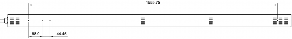
The SmartPDU has a height of approx. 178cm (40 height units) and thus fits into all common server cabinets from 42 height units. The SmartPDU delivers a maximum output power of up to 22kVA (depending on the version) and is therefore ideally suited for server racks with high power consumption. Depending on the version, the SmartPDU-40U is also available as a two-phase variant so that electronic terminal devices are protected against possible failures by two separate power supplies. The power is supplied via a 3 meter long connection cable and a CEE plug (IEC60309) corresponding to the design.
Safety instructions
No modifications of any kind may be made to Kentix GmbH products, with the exception of those described in the relevant instructions.
When installing Kentix devices, certain degrees of protection must be guaranteed.
Observe the relevant regulations for installations in the respective environment.
Only operate the products within the defined temperature range.
The instructions should be passed on to the user by the person carrying out the installation.
Kentix accepts no liability for damage to the devices or components caused by incorrect installation. Kentix accepts no liability for incorrectly programmed units.
Kentix accepts no liability for faults, material damage or other damage.
moisture, dirt and damage during transportation, storage and operation.
Only operate the products within the defined temperature range.
Installation and battery replacement may only be carried out by trained specialist personnel in accordance with the instructions.
Do not charge, short-circuit, open or heat batteries.
Observe the correct polarity when inserting the batteries.
The devices must always be operated with the batteries intended for the product.
When changing the batteries, always replace all batteries.
Dispose of old or used batteries properly.
Keep batteries out of the reach of children.
Controls
Front
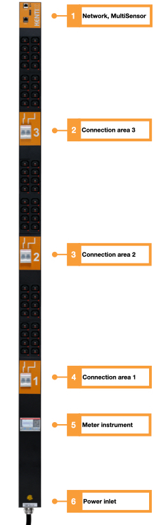
- Network connection (PoE) and Kentix system socket, Integrated sensors
- Connection area 3 (L3) with fuse C10/C16
- Connection area 2 (L2) with fuse C10/C16
- Connection area 1 (L1) with fuse C10/C16
- Current meter with display (MID calibrated) and residual current measurement (RCM) measurement
- Power connection depending on type 5-pole 16/32A or 3-pole 32A, cable length 3m
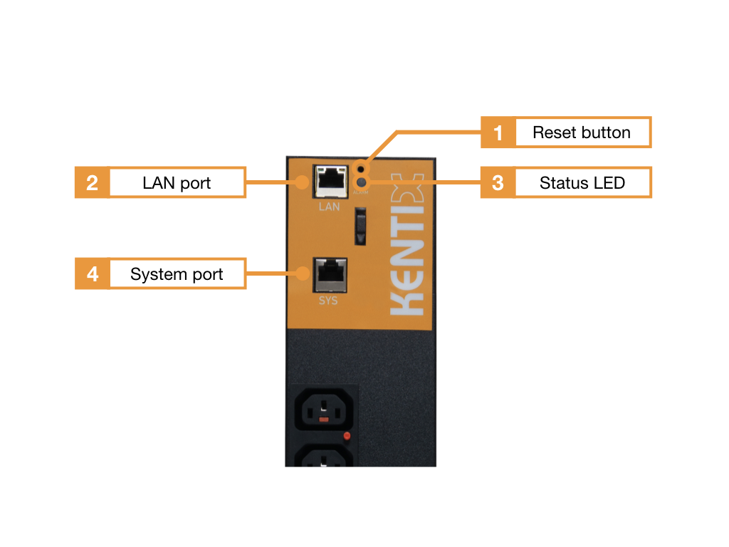
- Reset button
- Ethernet port with Power over Ethernet (100MBit, PoE Class 3)
- Status LED:
GREEN: POWER OK, no alarms pending
RED: POWER OK, alarms pending - Kentix system port (type B)
Top view
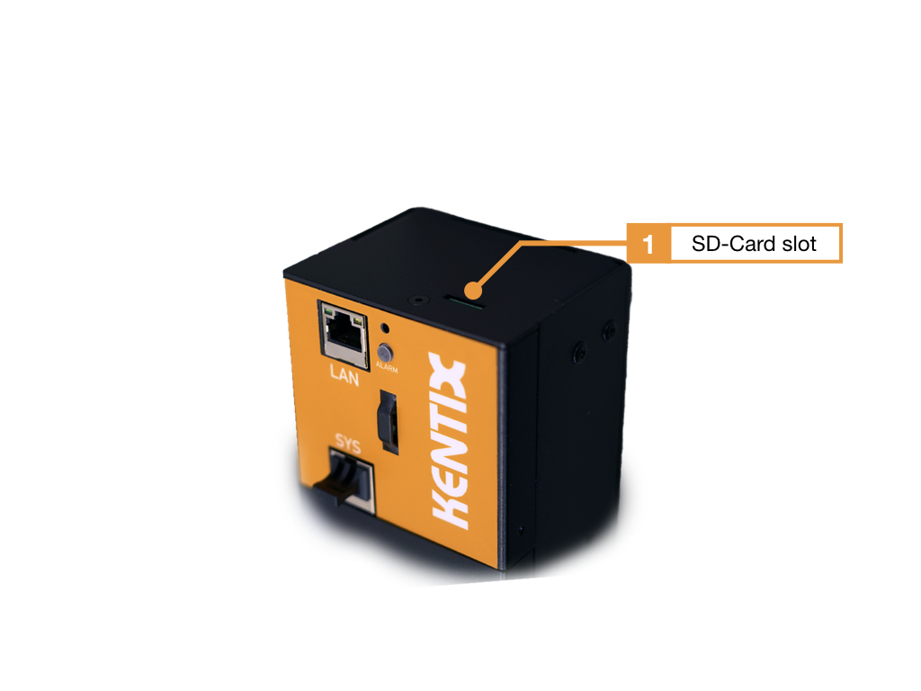
- MicroSD card slot
The SD card is required to perform a mass update or to save automatic data backups.
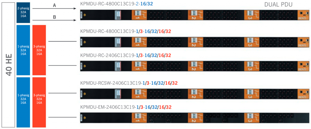
SmartPDU-40U variants
KPMDU- Type – Number of sockets – Connector plug
| Type | Description |
|---|---|
| KPMDU-RC- Number of sockets – connector plug | with residual current measurement (RCM) |
| KPMDU-RCSW- Number of sockets – connector plug | with residual current measurement (RCM) and sockets are switchable |
| KPMDU-EM- Number of sockets – connector plug | Passive PDU |
| Number of sockets | Description |
|---|---|
| KPMDU- Type -2406C13C19- Connector plug | 24x C13 sockets, 6x C19 sockets |
| KPMDU- Type -4800C13C19- Connector plug | 48x C13 sockets |
| Connector plug | Description |
|---|---|
| KPMDU- type – number of sockets -3-32 | 3-phase, 32A per phase |
| KPMDU- type – number of sockets -1-32 | 1-phase, 32A per phase |
| KPMDU- type – number of sockets -3-16 | 3-phase, 16A per phase |
| KPMDU- type – number of sockets -2-16 | 2x 1-phase, 16A per phase |
| KPMDU- type – number of sockets -2-32 | 2x 1-phase, 32A per phase |
| KPMDU- type – number of sockets -6-16 | 2x 3-phase, 16A per phase |
| ORDER-CODES |
|---|
| KPMDU-RC-2406C13C19-3-32 |
| KPMDU-RC-2406C13C19-1-32 |
| KPMDU-RC-2406C13C19-3-16 |
| KPMDU-RC-2406C13C19-1-16 |
| KPMDU-RC-4800C13C19-3-32 |
| KPMDU-RC-4800C13C19-1-32 |
| KPMDU-RC-4800C13C19-3-16 |
| KPMDU-RC-4800C13C19-1-16 |
| KPMDU-RC-4800C13C19-2-32 |
| KPMDU-RC-4800C13C19-2-16 |
| KPMDU-RC-4800C13C19-6-16 |
| KPMDU-RCSW-2406C13C19-3-32 |
| KPMDU-RCSW-2406C13C19-3-16 |
| KPMDU-RCSW-4800C13C19-3-32 |
| KPMDU-EM-2406C13C19-3-32 |
Functionalities
Cable fuse
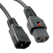
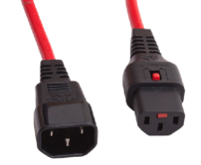
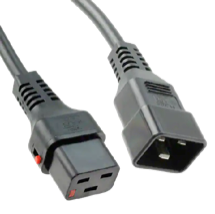
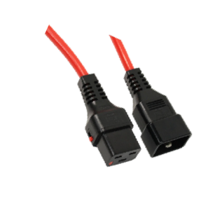
Each SmartPDU is equipped exclusively with IEC lock device sockets. This prevents accidental disconnection of the connection cables on the PDU side. When using the appropriate IEC-Lock connection cables, accidental disconnection of the connection cables at the terminal device is prevented. The connection cables are available in black and red.
Integrated residual current measurement (RCM): Testing according to DGUV V3
Depending on the version, the Kentix SmartPDU has an integrated residual current meter (RCM). This allows the plant inspection to be carried out in accordance with DGUV V3. This residual current measurement allows defective power supplies (server power supplies) to be detected at an early stage.
Circuit breaker
The SmartPDU is equipped with two circuit breakers per segment. All circuit breakers have type C tripping characteristics for increased inrush current. This ensures that in the event of a power failure and subsequent power recovery, the fuses are not immediately tripped by the inrush current when the connected terminal devices are started simultaneously. The inrush current can therefore be 5 times the rated current for a short time. Details of the current curve can be taken from the following diagram.
I1= Fixed non-tripping current at 30°C
I2= Fixed tripping current at 30°C
Factory settings
For initial configuration, use the IP address printed on the device or the address assigned via DHCP in a web browser (HTTPS). Please note the network settings of your connected PC.
The factory IP addresses at a glance:
| SiteManager and AlarmManager | 192.168.100.222 |
| MultiSensor | 192.168.100.223 |
| AccessManager | 192.168.100.224 |
| PowerManager | 192.168.100.225 |
| SmartPDU | 192.168.100.226 |
| Leakage sensor | 192.168.100.227 |
Reset to factory settings
- Restart the device (disconnect and reconnect the power supply).
- The status LED lights up briefly and then goes out.
- As soon as the status LED lights up green continuously, press and hold the reset button for 15 seconds until the device emits an acoustic feedback.
- The device loads the factory settings and performs a restart.
- After approx. 2 minutes, the device can be reached with the factory settings.
Assembly instructions
Mounting by means of mounting bracket
The SmartPDU-40U is mounted vertically in a server rack. Three mounting brackets are supplied with each SmartPDU-40U for mounting. These are used to mount the PDU to a 19 inch rack.
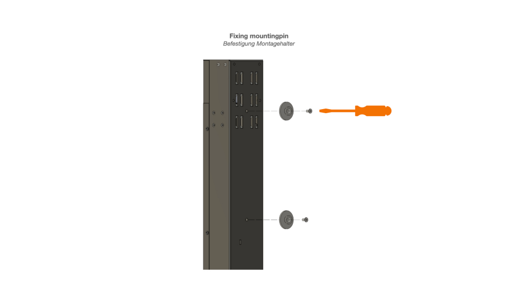
Assembly steps
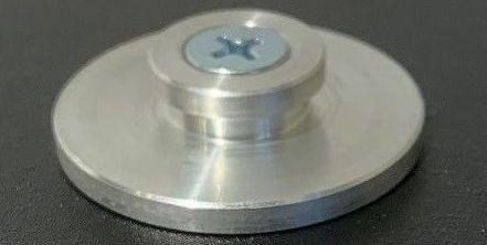
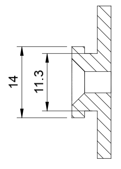
- Screw the mounting bracket to the PDU using countersunk screws (hexagon socket, width across flats: 2).
- Insert cage nuts (not included in scope of delivery)
- Screw PDU to the rack with mounting brackets

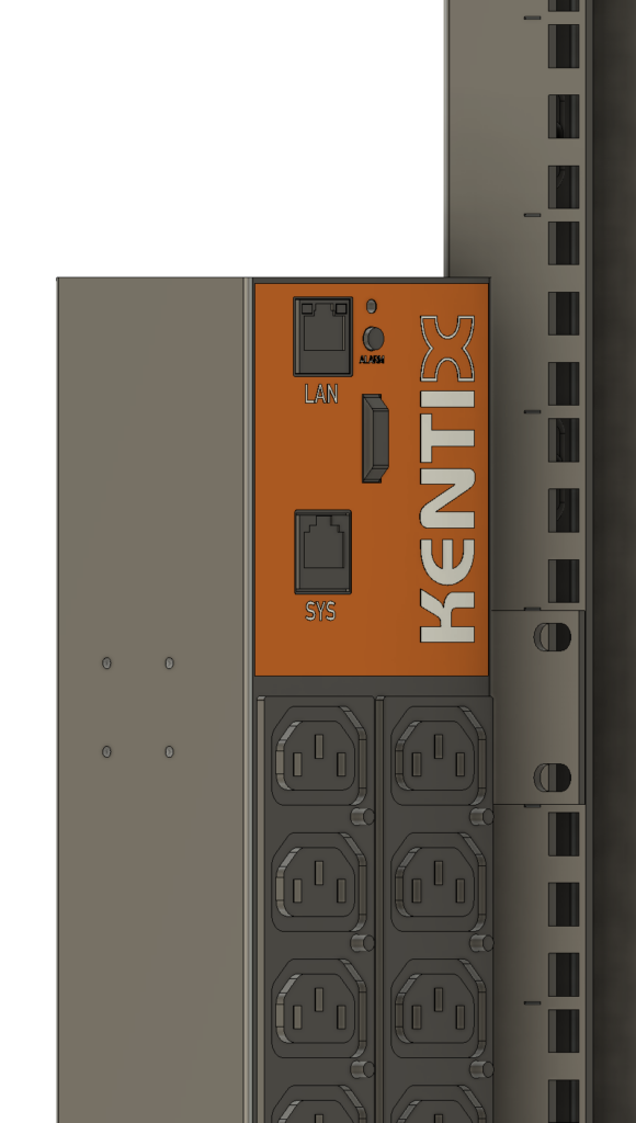
Mounting by means of quick mounting bracket
The quick mounting brackets are used to mount the SmartPDU on the rack if a suspension solution is available. The quick mounting bracket is screwed onto the back of the SmartPDU-40U. There are several holes for this purpose. Two quick mounting brackets must always be used to hang the PDU securely. These are not included with the SmartPDU and must be ordered separately (ORDER-CODE: KPMDU-MBR-1).
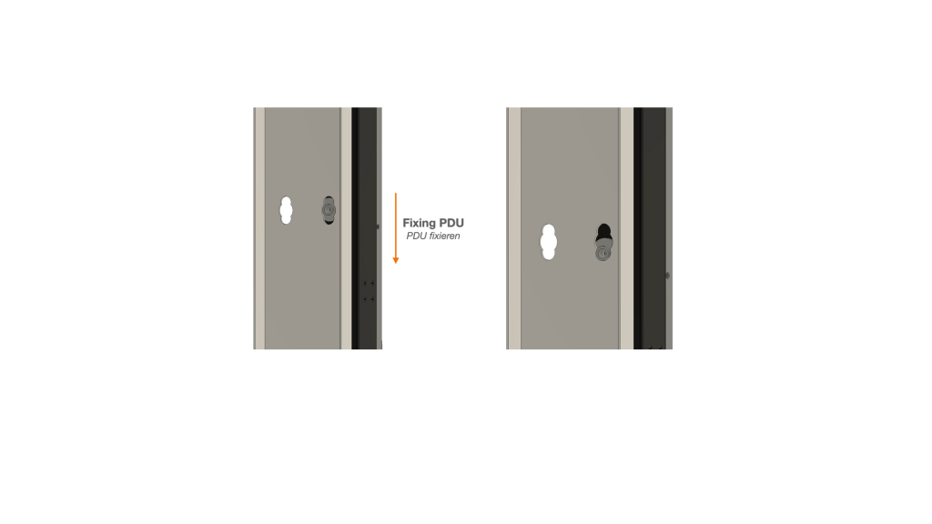
Assembly steps
- Screw quick mounting bracket to SmartPDU
- Hook SmartPDU into the existing suspension solution
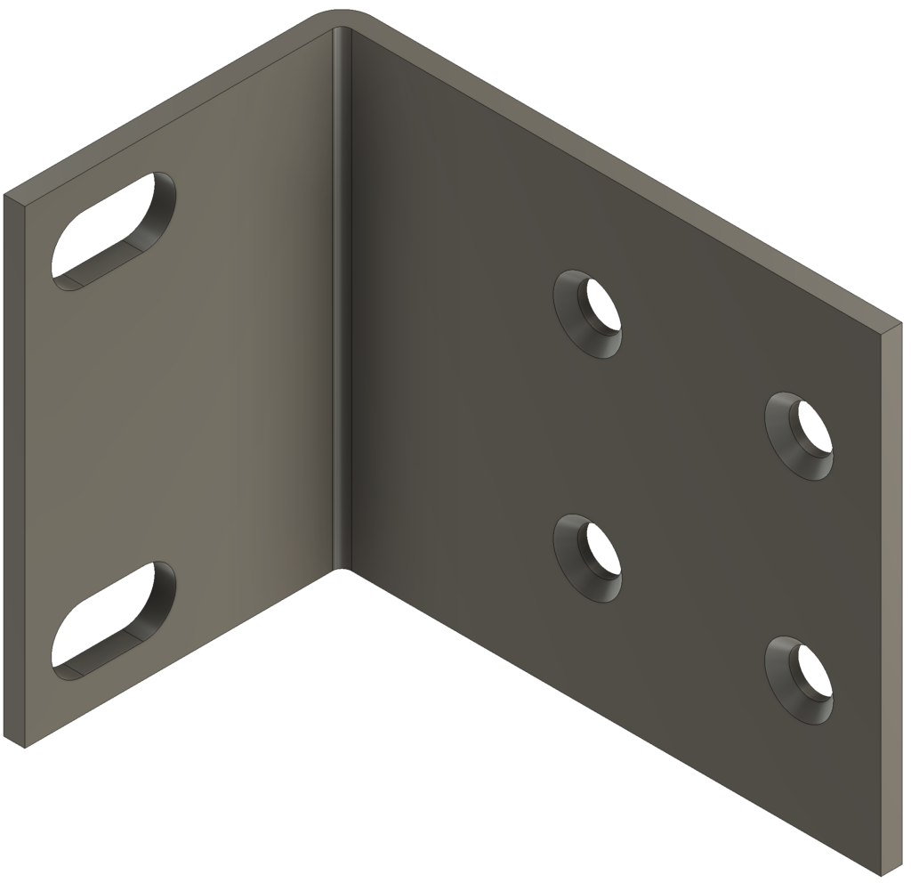
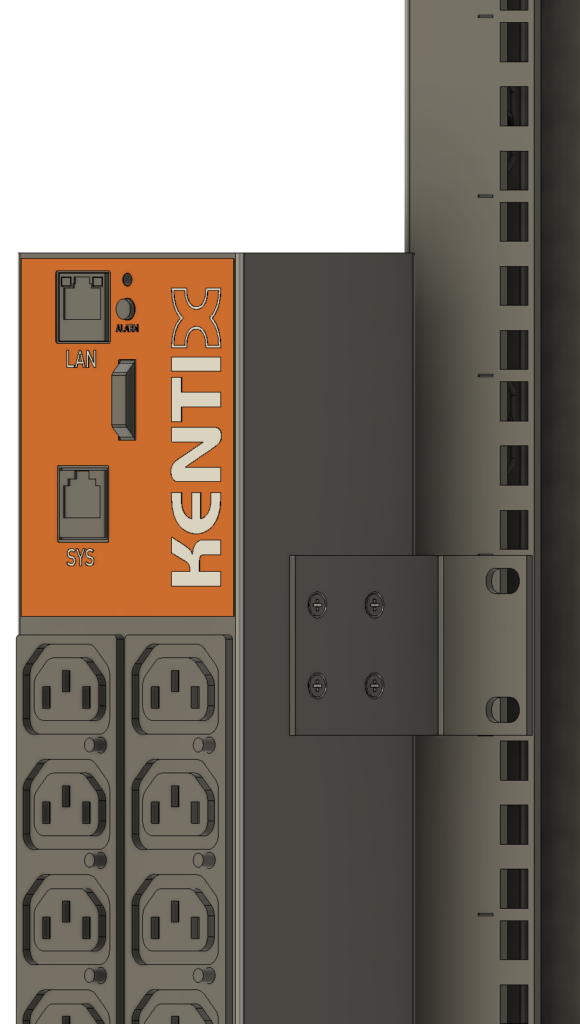
Fastening by means of mounting plates
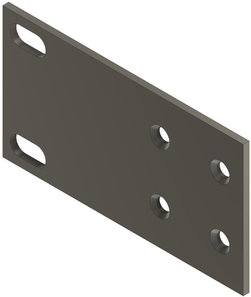
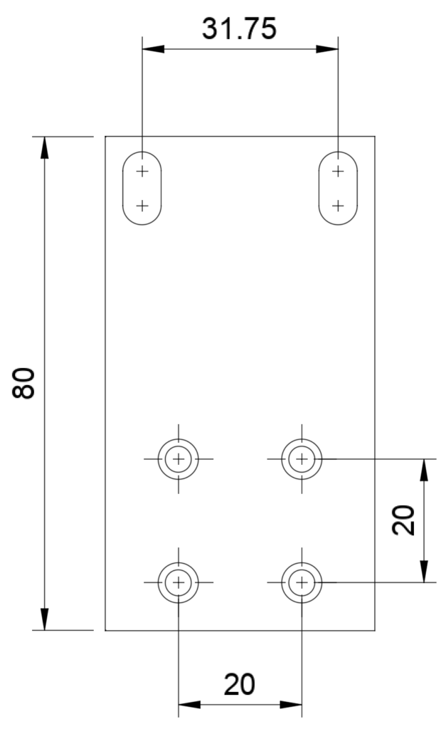
To mount the SmartPDU, mounting plates can be ordered separately, which allow it to be mounted at a 90° vertical angle to the mounting bracket (ORDER CODE: KPMDU-MBR-3).
Assembly steps
- Screw the mounting plates to the PDU using countersunk screws (hexagon socket, width across flats: 2)
- Insert cage nuts (not included in scope of delivery)
- Screw the PDU to the rack with mounting plates
Calibration of the room temperature measurement
Kentix MultiSensors record all important environmental values of a room, including the room temperature. In order to achieve the most accurate temperature possible and to trigger an alarm if the room temperature exceeds the limit value, we recommend calibrating the temperature measurement at the final installation location. This is especially necessary for sensors with Ethernet (PoE) connection, since a certain intrinsic heat falsifies the measurement. For MultiSensors with radio and battery supply, the influence of the intrinsic heat is not present.
However, in order to obtain a good measurement result with reproducible measured values in the event of an alarm, the MultiSensor should be calibrated to the respective installation location after installation. To do this, the temperature in the immediate vicinity (approx. 5-10 cm away) of the MultiSensor must be measured comparatively with a room thermometer that is as accurate as possible. If there is a deviation in temperature between the MultiSensor and the thermometer, the temperature value can be corrected. This is done by entering the determined temperature difference between the MultiSensor and the room thermometer as a correction offset in the KentixONE software. The correction also has a direct influence on the measurement of the relative humidity and on the dew point calculation of the MultiSensor.
| Step | Note |
|---|---|
| Install MultiSensor at the destination. | The position and orientation of the sensor should not be changed afterwards. Please note the following: – Mount with the X air opening facing downwards – Do not mount in the air flow – Ventilation vents of the sensor must be unobstructed |
| Perform configuration of the MultiSensor with Kentix ONE. | |
| At the earliest 30 minutes after commissioning , adjust the temperature of the MultiSensor to the room temperature. | To do this, measure the temperature with an external reference thermometer in the immediate vicinity, approx. 5-10 cm from the MultiSensor. It should be noted that this thermometer also acclimatizes to the room and displays the correct room temperature only after a few minutes. |
| If a difference between the MultiSensor and the thermometer is detected, this can be entered in the “Offset” field in the KentixONE configuration of the MultiSensor. After saving, the sensor then provides the corrected measured value. | The offset can only be specified by whole degrees, i.e. without decimal places. This results in an accuracy for the temperature of +/- 0.5 degrees. |
Configuration with KentixONE
The device is configured via the web browser in KentixONE. The device must be accessible to the central KentixONE instance on the network side. Depending on the device type, a communication key and the IP address or DHCP name of the central KentixONE instance must also be set on the device (MultiSensors, AccessManager, SmartPDU). IP cameras or IO modules, on the other hand, can be integrated directly into KentixONE.
All information about the software can be found in the KentixONE section and the associated documentation.