
Datasheet-KIO2217,
Datasheet-KIO2251,
Datasheet-KIO2260,
Quick guide
Overview
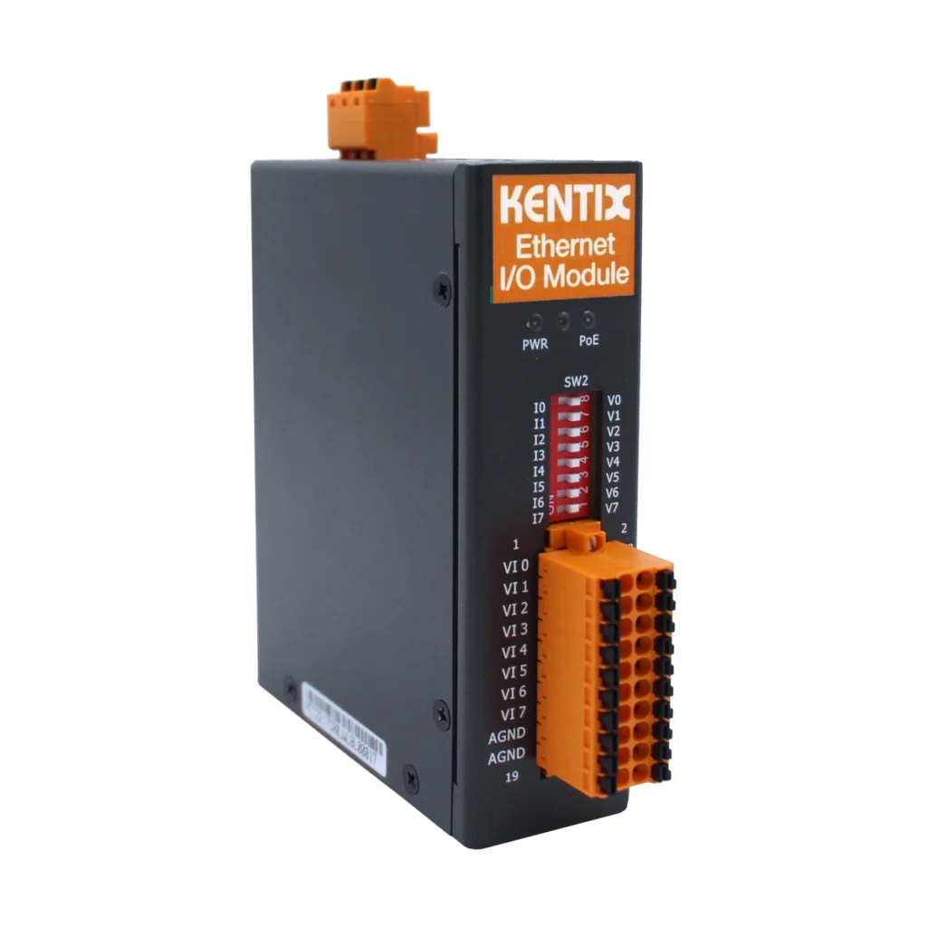
The expansion modules (Ethernet) integrate numerous inputs and outputs in a compact device. They enable the integration of external alarm messages and measured values in KentixONE. The network-compatible modules are supplied with power either via Power over Ethernet (PoE) or an external power supply unit (10-48 VDC, 4.4 W).
The network settings are configured on the device itself using a web browser. The alarm and display logic is then configured in KentixONE.
Safety instructions
No modifications of any kind may be made to Kentix GmbH products, with the exception of those described in the relevant instructions.
When installing Kentix devices, certain degrees of protection must be guaranteed.
Observe the relevant regulations for installations in the respective environment.
Only operate the products within the defined temperature range.
The instructions should be passed on to the user by the person carrying out the installation.
Kentix accepts no liability for damage to the devices or components caused by incorrect installation. Kentix accepts no liability for incorrectly programmed units.
Kentix accepts no liability for faults, material damage or other damage.
moisture, dirt and damage during transportation, storage and operation.
Only operate the products within the defined temperature range.
Installation and battery replacement may only be carried out by trained specialist personnel in accordance with the instructions.
Do not charge, short-circuit, open or heat batteries.
Observe the correct polarity when inserting the batteries.
The devices must always be operated with the batteries intended for the product.
When changing the batteries, always replace all batteries.
Dispose of old or used batteries properly.
Keep batteries out of the reach of children.
Variants
There are 3 expansion modules (Ethernet) available, which differ in the number of inputs and outputs. The differences are shown in the following table:
| Model | KIO2251 | KIO2217 | KIO2260 |
|---|---|---|---|
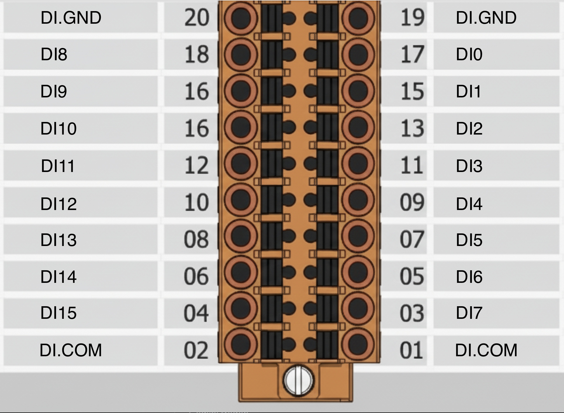 |  | 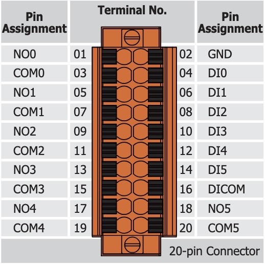 | |
| Digital inputs | 16 | – | 6 |
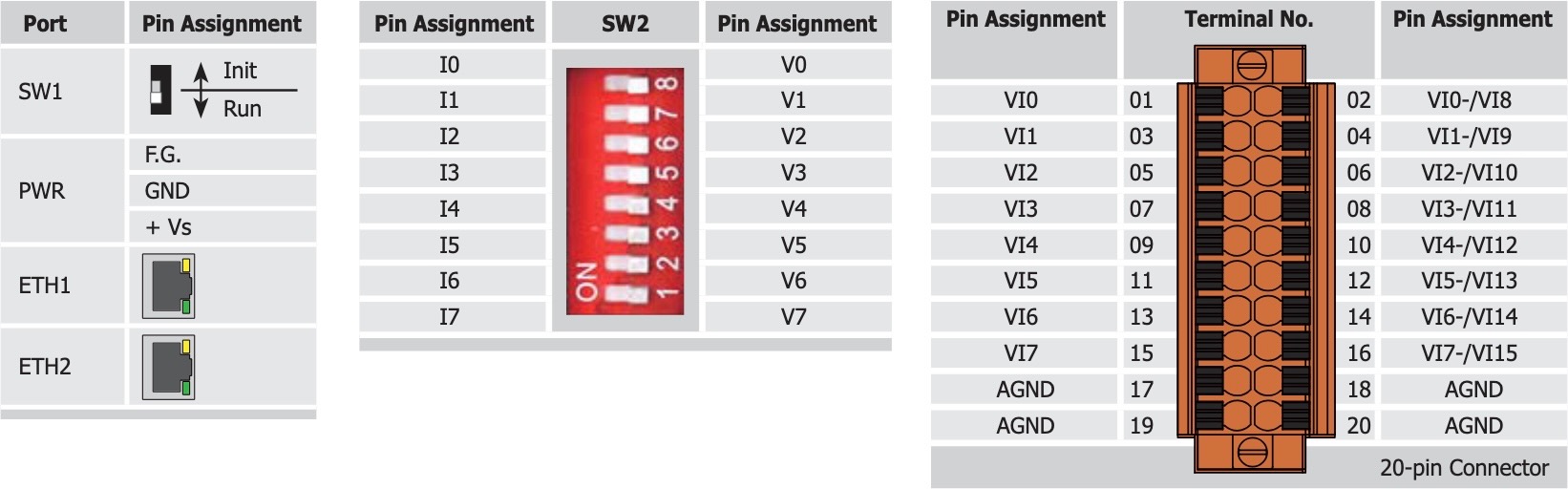
| Analog inputs | – | 8 differential or 16 single-ended | – |
| Relay outputs | – | – | 6 |
| Protocol | Modbus TCP | ||
| IP Port | 502 TCP | ||
| Configuration network | Web Server HTTP, Port 80, Default IP: 192.168.255.1 | ||
| Configuration via KentixONE | Configuration is carried out completely via KentixONE. Only IP settings on IO module necessary. Alarm and display logic is freely adjustable in KentixONE. | ||
| Power supply | PoE (Class 1) or external 10-48VDC | PoE (Class 1) or external 10-48VDC | PoE (Class 2) or external 10-48VDC |
| Mounting | DIN rail | ||
| Full of potential | |||
| Connection variant 1 | Floating SINK Readback as 1 +5 ~ +50VDC 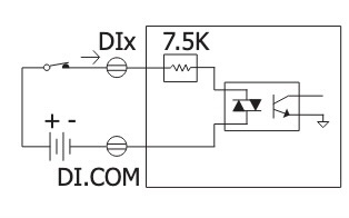 | Full-day input (single-ended mode) 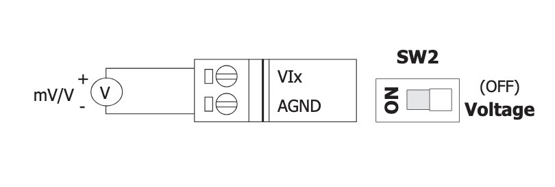 | Floating SINK Readback as 1 +10 ~ +50VDC 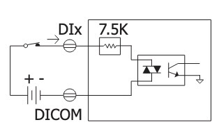 |
| Connection variant 2 | Floating SINK Readback as 0 OPEN or <1 VDC 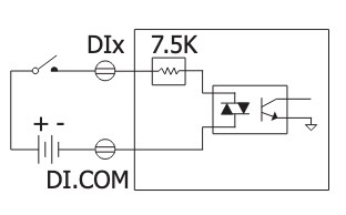 | – | Floating SINK Readback as 0 OPEN or <4 VDC 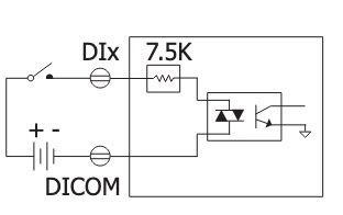 |
| Connection variant 3 | Floating SOURCE Readback as 1 +5 ~ +50 VDC 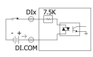 | – | Floating SOURCE Readback as 1 +10 ~ +50 VDC 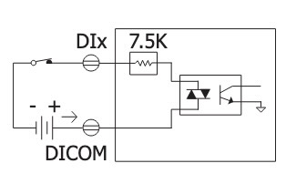 |
| Connection variant 4 | potential SOURCE Readback as 0 OPEN or <1 VDC 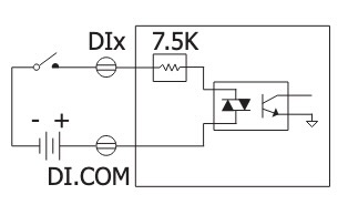 | – | potential SOURCE Readback as 0 OPEN or <4 VDC 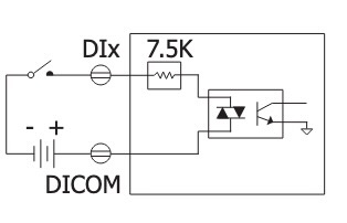 |
| Potential-free | |||
| Connection variant 5 | floating Close to GND Readback as 1 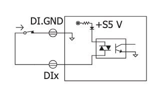 | Voltage Input (Differntial Mode)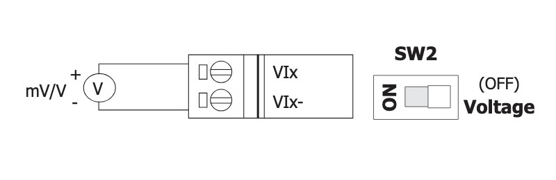 | floating Close to GND Readback as 1 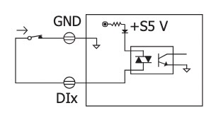 |
| Connection variant 6 | potential-free Open Readback as 0 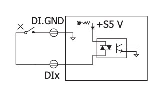 | Current Input (Differential Mode) 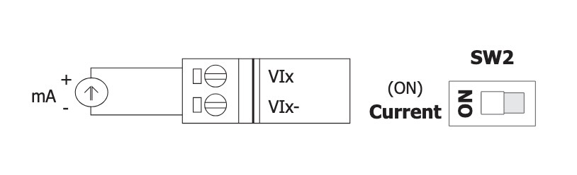 | potential-free Open Readback as 0 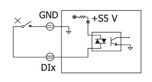 |
| Relay Output | |||
| Connection variant 7 | – | – | Relay output ON State Reedback as 1  |
| Connection variant 8 | – | – | Relay output OFF State Reedback as 0  |
Determination of the measuring range for KIO2217
To switch from voltage measurement ±10V (default) to current measurement ±20mA, the jumper inside the housing must be moved.
Factory settings
| Default IP address | 192.168.255.1 |
| Subnet mask | 255.255.255.0 |
Commissioning
The modules can be supplied with power either via Power over Ethernet (PoE, recommended) or via an external power supply unit. When using a power supply unit, please observe the power supply specifications in the Datasheet.
Configuration with KentixONE
The device is configured via the web browser in KentixONE. The device must be accessible to the central KentixONE instance on the network side. Depending on the device type, a communication key and the IP address or DHCP name of the central KentixONE instance must also be set on the device (MultiSensors, AccessManager, SmartPDU). IP cameras or IO modules, on the other hand, can be integrated directly into KentixONE.
All information about the software can be found in the KentixONE section and the associated documentation.