
ORDER CODES: KXC-50-30; KXC-50-30-SRR; KXC-50-30-SRL
These instructions show the installation of semi-locking cylinder KXC-50-30/-SRR/-SRL for Rittal comfort handles type TS, TS IT, SE, PC, IW (TS 8611.070).
In the following, the assembly of the semi-locking cylinders with and without spring return is explained.
Half cylinder with spring return (ORDER-CODES: KXC-50-AA-SRR/-SRL)
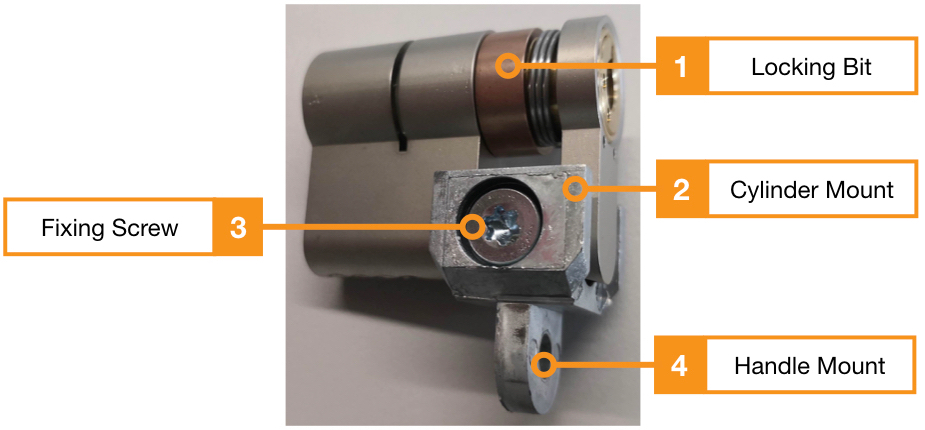
With the spring return principle, the knob can only be turned 90° and returns to its original position after the opening mechanism is actuated. The initial position of the locking bit (1) is explained in the following steps.
To enable the installation of the half cylinder in the comfort handle, the holder (2) must first be fastened to the half cylinder using the fastening screw (3).
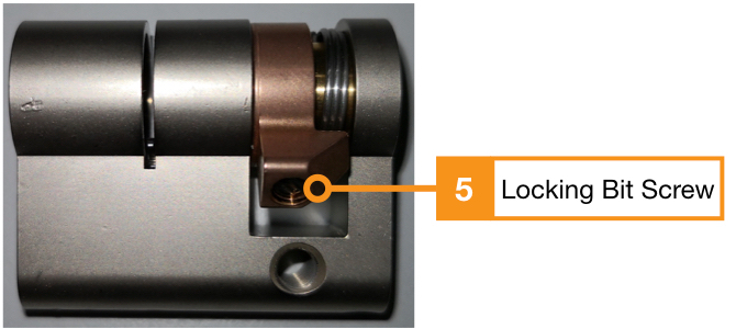
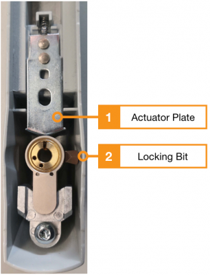
Please note that the locking bit (1) must be facing upwards to be able to reach the actuator plate of the Rittal handle. The position of the closing bar (1) can be adjusted by loosening the screw (5). After loosening the screw, the closing bit can be moved to the desired position.
To avoid permanent opening of the handle and problems when installing the cylinder in the handle housing, the locking bit should not be positioned directly against or under the actuator plate. (See Fig. 1 in the section “Inserting the half cylinder into the handle housing” in this document).
The positioning of the closing bar (1) should be selected 90° before the actual position of the opening mechanism.

Half cylinder without spring return (KXC-50-AA)
To enable the installation of the half cylinder in the comfort handle, the holder (2) must first be fastened to the half cylinder using the fastening screw (3).
Unlike the above-described locking cylinder with spring return, this variant does not require any positioning of the locking bit. In the case of the half cylinder without spring return, the locking bit can be rotated 360° in both directions.
Inserting the half cylinder into the handle housing
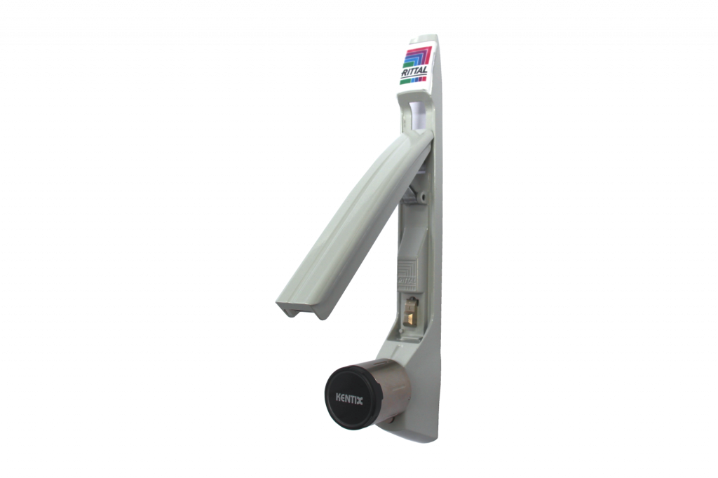
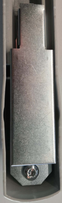
Now the half cylinder is inserted into the housing of the handle from behind and fastened with the enclosed screw. The opening for the lock must be visible from the front and the cylinder must not protrude over the edge of the housing.
For better visibility, the mudguard was not mounted for the example. This is fastened with the same screw as the cylinder, as can be seen in the second picture. This additionally serves to protect the actuator plate and locking cylinder.
Finally, the Kentix DoorLock-DC is pushed into the cylinder from the front until the DoorLock engages.