

Datasheet cXale SmartPDU-47U
KentixONE Operating mode
| SiteManager Operation | Stand-alone operation |
|---|---|
Overview
The cXale SmartPDU is optimized for the power supply of end devices in data and network cabinets. It enables power monitoring, consumption data logging and environmental monitoring and is typically mounted in a 19-inch rack. Up to 100 SmartPDUs can be easily managed using the integrated PowerManager and MultiSensor. The PowerManager is network-compatible and is supplied with voltage via Power over Ethernet (PoE).
The SmartPDU can be operated as a main device (operating mode: Main Device) or in a network (operating mode: “Satellite Device”) with other SmartPDUs. The KentixONE software is pre-installed via the integrated web server (HTTPS). Configuration is carried out via a web browser and, depending on the operating mode, locally on the SmartPDU itself (operating mode: Main Device) or on a central instance such as the “SiteManager” or “PowerManager” (operating mode: Satellite Device).
The SmartPDU is approx. 208 cm high (47 height units) and therefore fits into all standard server racks from 48 height units. It delivers a maximum output power of up to 22 kVA (depending on the version) and is therefore ideally suited for server racks with high power consumption. Depending on the version, the SmartPDU-47U is available with residual current measurement and overvoltage protection. The power is fed in via a three-meter connection cable and a CEE plug (IEC 60309) corresponding to the version.
Safety instructions
No modifications of any kind, other than those described in an appropriate manual, are permitted to Kentix GmbH products.
Certain levels of protection must be provided when installing Kentix equipment.
Observe the relevant regulations for installations in the respective environment.
Only operate the products within the defined temperature range.
The instructions should be passed on to the user by the person carrying out the installation.
Kentix accepts no liability for damage to the equipment or components resulting from incorrect installation. No liability is accepted for incorrectly programmed units.
Kentix shall not be liable in the event of malfunctions, damage to property or other damage.
Protect moisture, dirt and damage.
Only operate the products within the defined temperature range.
Installation and battery replacement may only be carried out by trained personnel in accordance with the instructions.
Do not charge, short circuit, open or heat batteries.
When inserting the batteries, pay attention to the correct polarity.
The devices must always be operated with the batteries intended for the product.
When changing batteries, always replace all batteries.
Dispose of old or used batteries properly.
Keep batteries out of the reach of children.
Controls
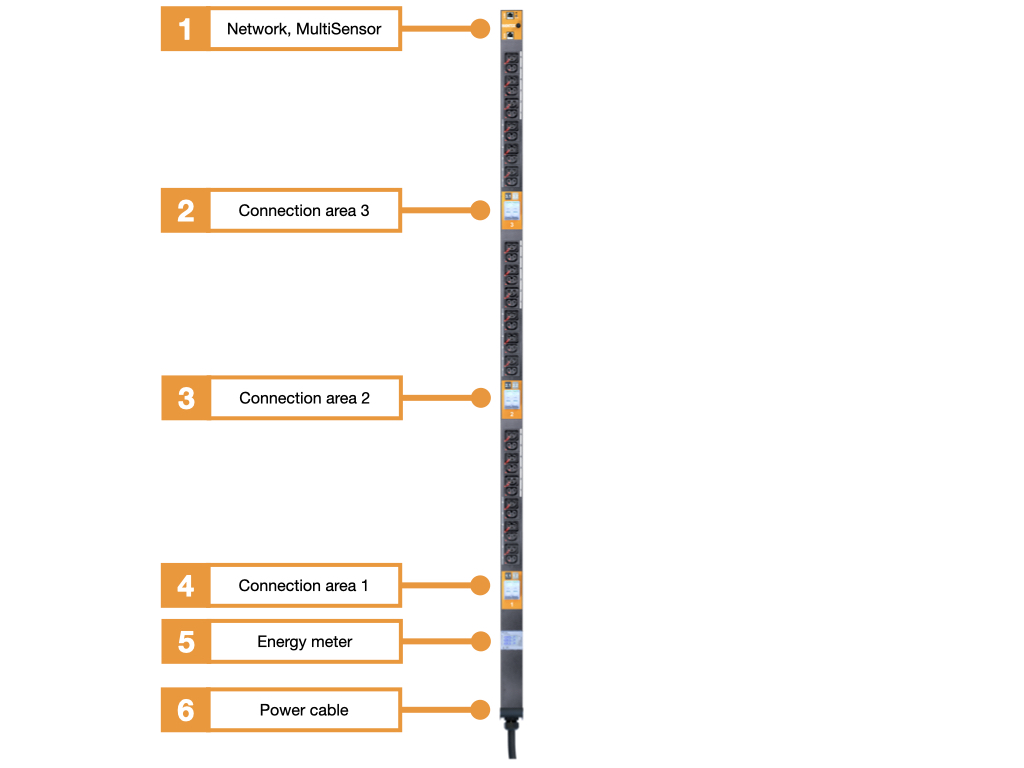
- Network connection and integrated MultiSensor
- Connection area 3 with two miniature circuit breakers
- Connection area 2 with two miniature circuit breakers
- Connection area 1 with two miniature circuit breakers
- Energy meter (MID calibrated)
- Connection cable, cable length 3m, with CEE plug (IEC 60309)
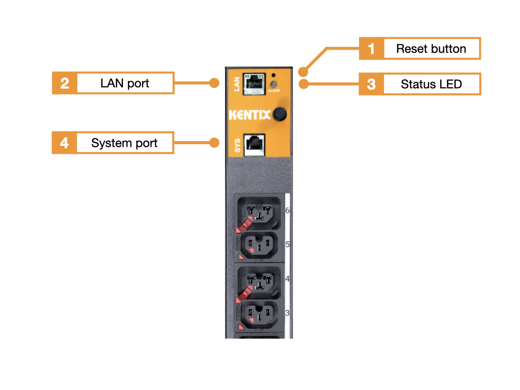
- Reset button
- Ethernet port with Power over Ethernet (100MBit, PoE Class 3)
- Status LED:
GREEN: POWER OK, no alarms pending
RED: POWER OK, alarms pending - Kentix system port (type B)
cXale SmartPDU-47U variants
Residual current measurement – Switchable – Overvoltage protection
| Type | with residual current measurement | with overvoltage protection |
|---|---|---|
| KPMDU-xx-xx-xx-2424 connector plug | ||
| KPMDU-RC-xx-xx-2424 connector plug | ||
| KPMDU-RC-xx-SP-2424 connector plug |
Number of sockets
| Number of sockets | C13 sockets | Cx sockets |
|---|---|---|
| KPMDU type 2424connector plug | 24 | 24 |
Connector plug
| Connector plug | Description |
|---|---|
| KPMDU type-2424-3-32 | 3-phase, 32A per phase |
| KPMDUtype-2424-3-16 | 3-phase, 16A per phase |
| KPMDU type-2424-1-32 | 1-phase, 32A per phase |
Functionalities
Cable fuse
All SmartPDUs are exclusively equipped with IEC-Lock appliance sockets. This prevents the connection cables from being accidentally pulled out on the side of the PDU. When using the appropriate IEC-Lock connection cables, accidental unplugging of the cables at the end device is also prevented. The connection cables are available in black and red.
Each cXale SmartPDU-40U also has 24 C13 sockets and 24 Cx combi sockets. The Cx combi socket outlet is compatible with C14, C16, C20 and C22 plugs.
Integrated residual current measurement (RCM): Testing according to DGUV V3
Depending on the version, the Kentix SmartPDU has an integrated residual current meter (RCM). This allows fault currents caused by defective server power supplies, for example, to be detected at an early stage before they lead to damage, fires or other dangerous situations. This enables system testing in accordance with DGUV V3.
Overvoltage protection
Depending on the version, a type 2+3 surge arrester is installed in the SmartPDU. Overvoltages from atmospheric discharges and switching overvoltages lead to interference energy. An effective surge protection concept gradually reduces this to a harmless level. Such a concept includes coarse protection (type 1), medium protection (type 2) and fine protection (type 3). The overvoltage protection integrated in the SmartPDU covers the medium and fine protection. It is used to protect people and end devices against overvoltages from atmospheric discharges and switching operations.
Circuit breaker
The SmartPDU is equipped with two circuit breakers per segment. All circuit breakers have type C tripping characteristics for increased inrush current. This ensures that in the event of a power failure and subsequent power recovery, the fuses are not immediately tripped by the inrush current when the connected terminal devices are started simultaneously. The inrush current can therefore be 5 times the rated current for a short time. Details of the current curve can be taken from the following diagram.
Factory settings
For initial configuration, use the IP address printed on the device or the address assigned via DHCP in a web browser (HTTPS). Please note the network settings of your connected PC.
The factory IP addresses at a glance:
| SiteManager and AlarmManager | 192.168.100.222 |
| MultiSensor | 192.168.100.223 |
| AccessManager | 192.168.100.224 |
| PowerManager | 192.168.100.225 |
| SmartPDU | 192.168.100.226 |
| Leakage sensor | 192.168.100.227 |
Reset to factory settings
- Restart the device (disconnect and reconnect the power supply).
- The status LED lights up briefly and then goes out.
- As soon as the status LED lights up green continuously, press and hold the reset button for 15 seconds until the device emits an acoustic feedback.
- The device loads the factory settings and performs a restart.
- After approx. 2 minutes, the device can be reached with the factory settings.
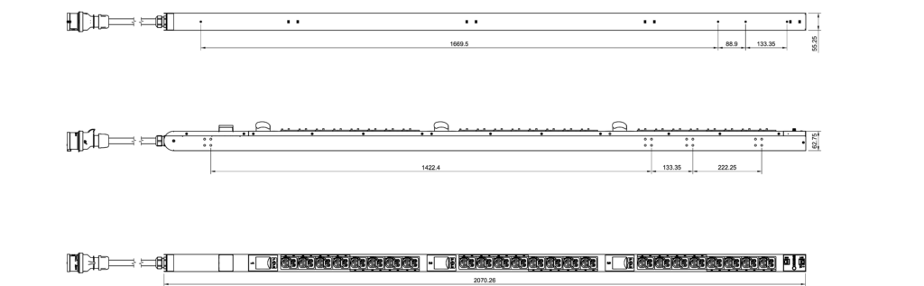
Dimensions
Calibration of the room temperature measurement
Kentix MultiSensors record all important environmental values of a room, including the room temperature. In order to achieve the most accurate temperature possible and to trigger an alarm if the room temperature exceeds the limit value, we recommend calibrating the temperature measurement at the final installation location. This is especially necessary for sensors with Ethernet (PoE) connection, since a certain intrinsic heat falsifies the measurement. For MultiSensors with radio and battery supply, the influence of the intrinsic heat is not present.
However, in order to obtain a good measurement result with reproducible measured values in the event of an alarm, the MultiSensor should be calibrated to the respective installation location after installation. To do this, the temperature in the immediate vicinity (approx. 5-10 cm away) of the MultiSensor must be measured comparatively with a room thermometer that is as accurate as possible. If there is a deviation in temperature between the MultiSensor and the thermometer, the temperature value can be corrected. This is done by entering the determined temperature difference between the MultiSensor and the room thermometer as a correction offset in the KentixONE software. The correction also has a direct influence on the measurement of the relative humidity and on the dew point calculation of the MultiSensor.
| Step | Note |
|---|---|
| Install MultiSensor at the destination. | The position and orientation of the sensor should not be changed afterwards. Please note the following: – Mount with the X air opening facing downwards – Do not mount in the air flow – Ventilation vents of the sensor must be unobstructed |
| Perform configuration of the MultiSensor with Kentix ONE. | |
| At the earliest 30 minutes after commissioning , adjust the temperature of the MultiSensor to the room temperature. | To do this, measure the temperature with an external reference thermometer in the immediate vicinity, approx. 5-10 cm from the MultiSensor. It should be noted that this thermometer also acclimatizes to the room and displays the correct room temperature only after a few minutes. |
| If a difference between the MultiSensor and the thermometer is detected, this can be entered in the “Offset” field in the KentixONE configuration of the MultiSensor. After saving, the sensor then provides the corrected measured value. | The offset can only be specified by whole degrees, i.e. without decimal places. This results in an accuracy for the temperature of +/- 0.5 degrees. |
Configuration with KentixONE
The device is configured via the web browser in KentixONE. The device must be accessible to the central KentixONE instance on the network side. Depending on the device type, a communication key and the IP address or DHCP name of the central KentixONE instance must also be set on the device (MultiSensors, AccessManager, SmartPDU). IP cameras or IO modules, on the other hand, can be integrated directly into KentixONE.
All information about the software can be found in the KentixONE section and the associated documentation.