
DATASHEET LEAKAGE SENSOR
KentixONE Operating mode
| SiteManager Operation | Stand-alone operation |
|---|---|
Overview
The Ethernet leakage sensor enables the reliable detection of water and other conductive liquids and represents a consistent further development of the previous sensor technology and functionality. In contrast to previous versions, the sensor is connected directly via Ethernet (PoE) and can therefore be installed independently of other Kentix devices with digital inputs.
The sensor is equipped with a highly sensitive integrated point sensor on the underside, which is triggered by a quantity of water from approx. 5 ml on an area of 5 × 5 cm. The leakage sensor also has two sensor cables (rope sensors) made of conductive polymer material. These are available in lengths of 2 x 10 m or 2 x 20 m. The trigger sensitivity of the rope sensors, for example, is approx. 5 ml of water over a cable length of 20 cm. Both the point sensor and the rope sensors can be parameterized on the software side so that the sensitivity can be individually adjusted. The measurements are carried out independently of each other and enable parallel operation of both Rope sensors as well as a separate point measurement.
To increase operational safety, the leakage sensor has integrated sabotage detection by means of a 3-axis acceleration sensor with position detection, so that unauthorized movements, position changes or manipulation attempts can be detected.
Evaluation and configuration is carried out via the integrated KentixONE software using an integrated web server, so that the leakage sensor can also be operated as a stand-alone device without additional Kentix systems.
Safety instructions
No modifications of any kind, other than those described in an appropriate manual, are permitted to Kentix GmbH products.
Certain levels of protection must be provided when installing Kentix equipment.
Observe the relevant regulations for installations in the respective environment.
Only operate the products within the defined temperature range.
The instructions should be passed on to the user by the person carrying out the installation.
Kentix accepts no liability for damage to the equipment or components resulting from incorrect installation. No liability is accepted for incorrectly programmed units.
Kentix shall not be liable in the event of malfunctions, damage to property or other damage.
Protect moisture, dirt and damage.
Only operate the products within the defined temperature range.
Installation and battery replacement may only be carried out by trained personnel in accordance with the instructions.
Do not charge, short circuit, open or heat batteries.
When inserting the batteries, pay attention to the correct polarity.
The devices must always be operated with the batteries intended for the product.
When changing batteries, always replace all batteries.
Dispose of old or used batteries properly.
Keep batteries out of the reach of children.
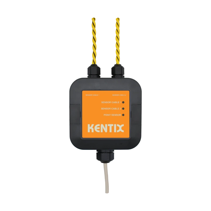
Controls
Front
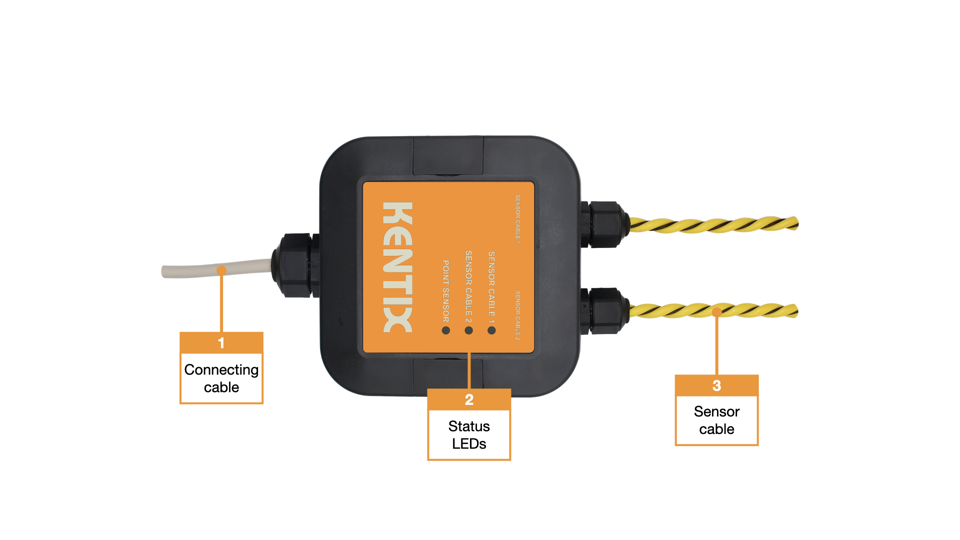
- Connection cable
- Status LEDs :
GREEN: POWER OK, no alarms pending per sensor
RED: Power OK, alarms pending per sensor - Sensor cable
Back
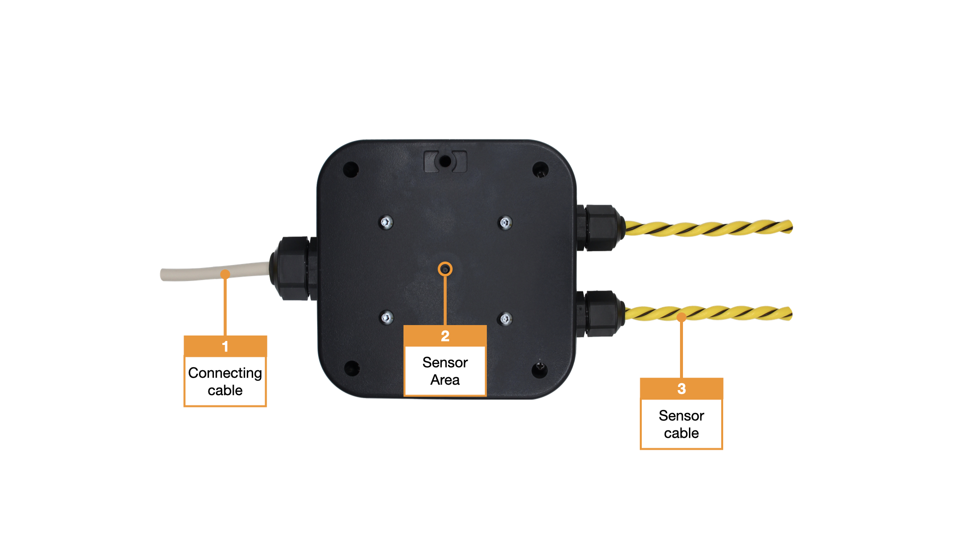
- Connection cable
- Housing sensor
- Sensor cable
Detection and sensitivity
Why are there different sensitivities for point and rope sensors?
The sensitivity of leakage sensors is influenced by several environmental factors. These include the residual moisture of surfaces, very high humidity and surfaces with low electrical conductivity, for example due to an ESD coating. These influences can usually be compensated for by adjusting the sensor sensitivity. Temperature fluctuations, on the other hand, are more critical, especially if the temperature falls below the dew point and condensation forms, as this can lead to unintentional triggering.
One of the main reasons for different sensitivities is the design and application range of the respective sensor types. The point sensor reacts locally to liquid. Its sensitivity is designed in such a way that even about 5 ml Water can be detected on an area of 5 cm × 5 cm. This punctual measurement is particularly suitable for clearly defined monitoring points where liquid can collect in a targeted manner. The specified value is specified again in the final Datasheet.
The rope sensor, on the other hand, monitors a longer distance. Here, the amount of liquid detected is distributed over the length of the sensor. The sensitivity is designed so that around 5 ml of water is reliably detected over a sensor length of 20 cm. This makes the rope sensor particularly suitable for area or linear monitoring, for example along pipes, under raised floors or in technical rooms.
In summary, the different sensitivities result from the design, the monitored area or length and the intended use of the sensors. Both sensor types are matched in such a way that they enable reliable and practical leakage detection in their respective areas of application.
Factory settings
For initial configuration, use the IP address printed on the device or the address assigned via DHCP in a web browser (HTTPS). Please note the network settings of your connected PC.
The factory IP addresses at a glance:
| SiteManager and AlarmManager | 192.168.100.222 |
| MultiSensor | 192.168.100.223 |
| AccessManager | 192.168.100.224 |
| PowerManager | 192.168.100.225 |
| SmartPDU | 192.168.100.226 |
| Leakage sensor | 192.168.100.227 |
Reset to factory settings
- The housing must be opened to reset the leakage sensor.
- Restart the device (disconnect and reconnect the power supply).
- The status LED lights up briefly and then goes out. (The status LED is located under the circuit board when it is open)
- As soon as the status LED lights up green continuously, press and hold the reset button for 15 seconds. (The start-up process after the power supply has been restored takes about 1:30 minutes until the status LED lights up green again).
- The device loads the factory settings and performs a restart.
- After approx. 2 minutes, the device can be reached with the factory settings.
Assembly instructions
The KLS-ETH can be attached directly to the surface without opening the housing. It can be mounted either by gluing or screwing.
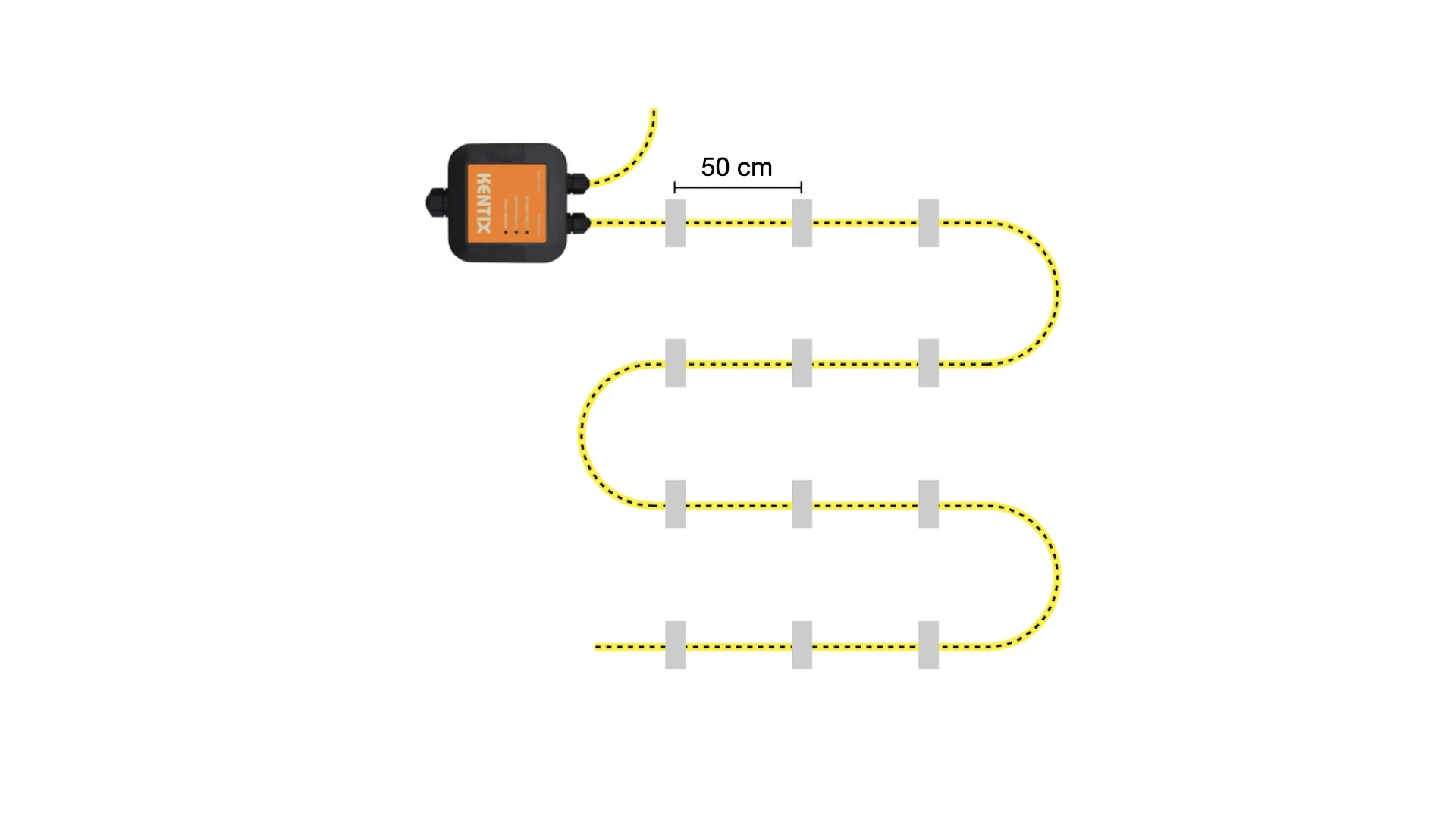
The sensor cable is equipped with fastening straps and should be fixed along the surface. A recommended distance of around 0.5 m should be maintained between the individual fixing points. The lugs are primarily intended for bonding to the substrate. A suitable silicone adhesive is recommended for bonding to ensure permanent adhesion. Alternatively, the brackets can also be screwed if this is structurally necessary.
The KLS-ETH and the sensor cable should only be installed on dry and clean surfaces to ensure secure mounting and reliable operation. For optimum detection, it is recommended that the sensor is installed at the lowest point of the area to be monitored.
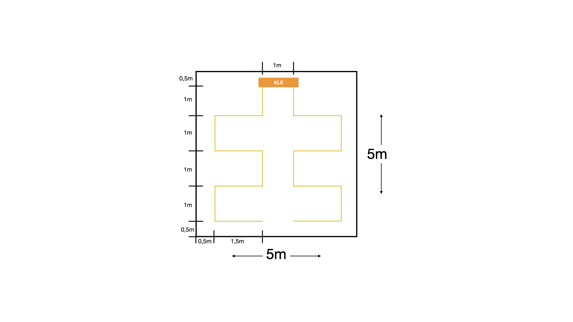
Example monitoring
The following illustration shows an example installation of the KLS-ETH-2-10 for monitoring a square area of approx. 25 m² (width approx. 5 m, length approx. 5 m).
Structure and placement
The KLS-ETH-2-10 is positioned centrally at the top edge of the monitored area. From there, the room is scanned line by line. The lines shown in yellow visualize the internal scanning grid of the sensor.
Configuration with KentixONE
The device is configured via the web browser in KentixONE. The device must be accessible to the central KentixONE instance on the network side. Depending on the device type, a communication key and the IP address or DHCP name of the central KentixONE instance must also be set on the device (MultiSensors, AccessManager, SmartPDU). IP cameras or IO modules, on the other hand, can be integrated directly into KentixONE.
All information about the software can be found in the KentixONE section and the associated documentation.